Component Picking
Overview
This section will cover the practical considerations for selecting the physical components for your passive crossover. In the previous sections, we've designed our driver configurations and simulated our crossover circuits to achieve a target frequency response. Now, we must translate that on-paper design into a set of real-world, physical components.
Keep in mind that for IEMs, our single greatest constraint is physical space. This will heavily influence every choice we make. This guide will provide the basic information on component types, their common "form factors," and what to look for when purchasing the resistors, capacitors, and wires needed to build your circuit.
The Form Factor: SMD (Surface-Mount Device)
When you imagine a resistor or capacitor, you might picture a component with long wire "legs" (known as "through-hole"). These are far too large for an IEM. Instead, the DIY IEM world relies exclusively on SMD (Surface-Mount Device) components.
These are tiny, rectangular components with no legs. They are designed to be soldered directly onto the surface of a PCB (Printed Circuit Board) or, in our case, directly to each other and the driver terminals.

Understanding Package Size
SMD components are identified by a 4-digit code, like 0805 or 0603. This code represents the physical length and width of the component in imperial units.
- 0805: 0.08 inches by 0.05 inches (approx. 2.0mm x 1.25mm)
- 0603: 0.06 inches by 0.03 inches (approx. 1.6mm x 0.8mm)
- 0402: 0.04 inches by 0.02 inches (approx. 1.0mm x 0.5mm, extremely small)
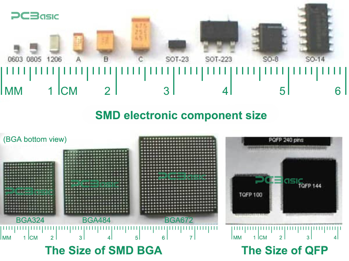
For our purposes, the 0805 and 0603 package sizes are the most common. 0805 is larger and generally easier to handle and solder by hand. 0603 is significantly smaller, saving precious space but requiring more soldering precision. For your first build, starting with 0805 components is highly recommended.
A Note on Through-Hole Components
Even though we usually use SMD components, you can use through-hole ones if you are soldering point-to-point (without a PCB). If you must use them, I would strongly recommend 1/8W (one-eighth watt) rating through-hole resistors. They are small enough that they can often be fit inside an IEM shell, and they are available in all the common values you will need for tuning.
Selecting Resistors (R)
In our crossover circuits, resistors are used for attenuation (to reduce a driver's loudness) and damping (to control impedance peaks).
- Type: Thick Film or Thin Film resistors are the standard. Thin film resistors are often preferred for high-precision audio work due to lower noise and better stability, but thick film is more common and perfectly acceptable.
- Package Size: 0805 or 0603.
- Tolerance: This is how accurate the resistor's value is. You will see 5% and 1% tolerance. For crossover work, ≤1% tolerance is strongly recommended to ensure your filters behave as you calculated in the simulation.
- Power Rating: You will see ratings like 1/8W or 1/10W. Given the extremely low power levels inside an IEM, any standard SMD resistor rating will be more than sufficient.
Selecting Capacitors (C)
Capacitors are the most critical component for our filters, and their physical properties matter greatly. We primarily use them to create high-pass filters (blocking bass from tweeters) and, in our RC-only designs, low-pass filters (shunting highs to ground).
There are two main types you will encounter:
1. Multi-Layer Ceramic Capacitors (MLCC)
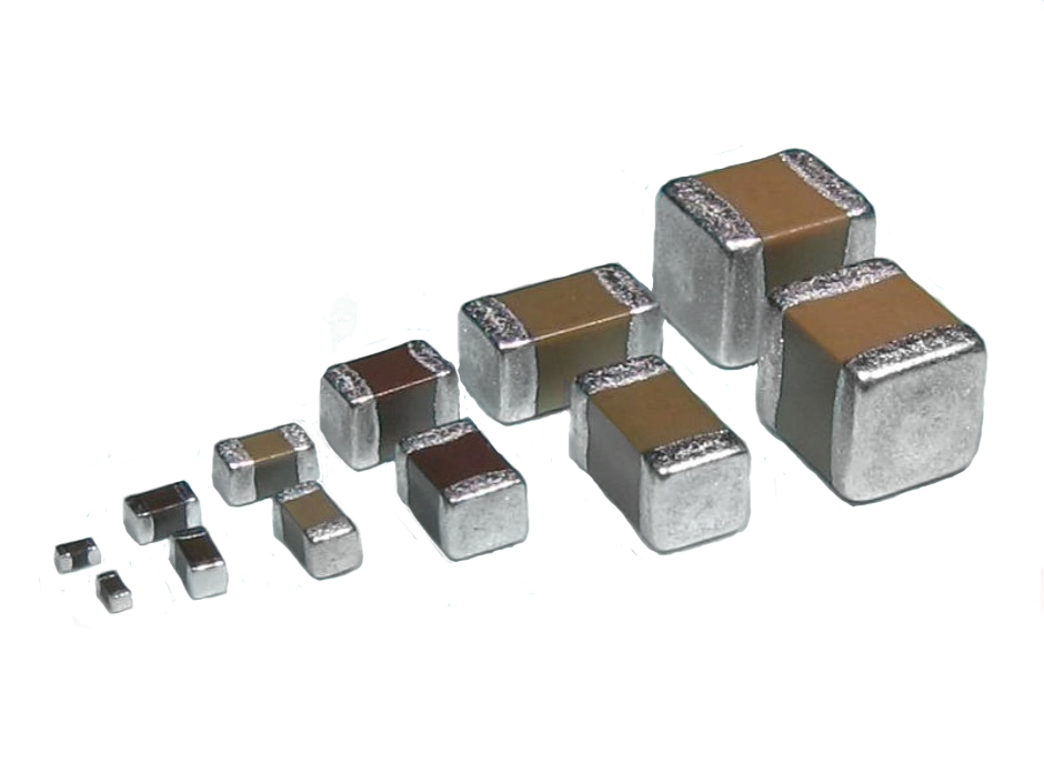
These are the most common type used in IEMs for one simple reason: they are incredibly small.
- Pros: Very high capacitance values in tiny packages (e.g., 1uF, 4.7uF, 10uF in an 0805 package).
- Cons: Can be microphonic (vibrations can induce noise, though this is rare in an IEM) and can be non-linear (their capacitance can change with the voltage applied).
- Dielectric (The Important Part):
- C0G/NP0: Extremely stable and perfect for audio. They are not microphonic and have 0% voltage coefficient. However, they are typically only available in small values (pico-farads (pF) or low nano-farads (nF)).
- X7R / X5R: These are the workhorses. They are less stable than C0G but are the only way to get high capacitance values (like 1uF to 22uF) in a small 0805 package. We must accept their non-ideal properties as a trade-off for their small size.
Recommendation: For any filter values above ~100nF (0.1uF), you will almost certainly be using X7R or X5R MLCCs.
2. Film Capacitors
These are the "audiophile-grade" capacitors (e.g., PPS, PET, PEN).
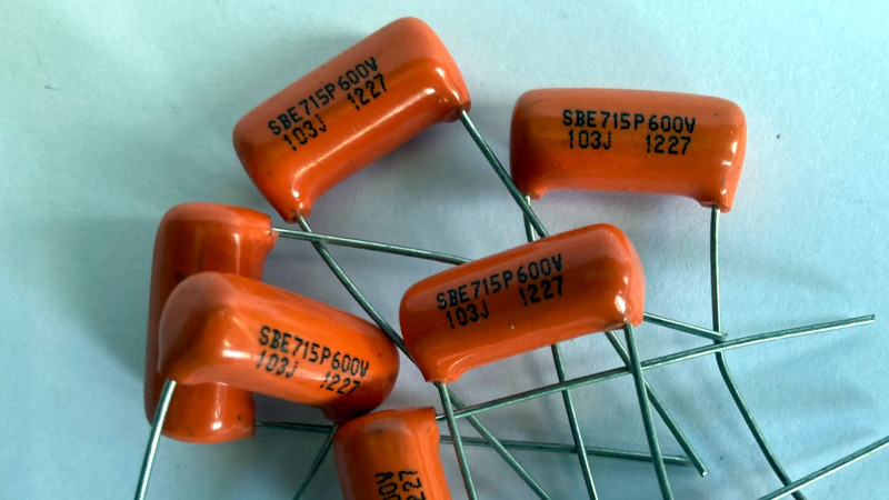
- Pros: Excellent for audio. Very stable, non-microphonic, and have a very low distortion profile.
- Cons: They are massive. A 1uF film capacitor can be larger than a balanced armature driver itself, making it almost impossible to use in a compact IEM shell.
Conclusion: While film capacitors are technically superior for audio, MLCCs are the practical and necessary choice for nearly all DIY IEM crossovers due to the extreme space constraints.
Selecting Inductors (L)
As mentioned in the Crossover-Tuning guide, we generally avoid inductors in IEM design.

- Size: They are physically large coils of wire, making them very difficult to fit. You can try to find smaller wattage-rated ones, but they will still be hard to fit.
- Interference: Their magnetic field can interfere with the magnetic fields of the drivers (especially BAs), which can induce noise and distortion.
It's important to remember that the crossover isn't everything. The driver components are the main thing. If you pick bad drivers in the beginning, trying to make a good crossover for them will be really, really hard. So, pick drivers that complement each other in terms of one producing the sound the other can't. Don't buy two drivers that produce a large amount of the same sound—for example, two mid-focused woofers. It then becomes very difficult to cut a lot of that mid-range out of the woofer.
(Don't ask me how I know 😭)
Selecting Internal Wiring
You will need thin, flexible, and high-quality wire to connect your components, drivers, and the 2-pin/MMCX connector.

- Type: Litz Wire is the standard.
- Why Litz?
- Flexibility: It is incredibly flexible, making it easy to route inside a cramped shell.
- Prevents Skin Effect: At high frequencies, AC current tends to travel on the "skin" of a wire. In a single thick wire, this increases resistance at high frequencies. Litz wire's many tiny strands prevent this, ensuring a clear treble signal.
- Gauge: A high AWG (American Wire Gauge) is used, meaning the wire is very thin. Common choices are 38 AWG to 44 AWG, but slightly higher gauges can fit; its not a hard and fast rule by any means.
Where to Buy Components
- Mouser or Digi-Key: These are professional electronics distributors. They have the highest quality components, sell genuine parts, and provide detailed datasheets for everything. This is the best choice for high-quality, reliable components.
- Amazon or AliExpress: You can find "SMD Component Kits" or "Component Books" on these sites. These contain a large assortment of 0805 or 0603 resistors and capacitors in many different values.
- Pros: Extremely cheap and a great way to get a wide variety of values for experimentation.
- Cons: Quality and tolerance can be inconsistent. You are less certain of the exact capacitor dielectric (e.g., X7R vs Y5V).
For your first build, an SMD component book/kit is a very cost-effective way to get started, as you will likely be changing component values many times during the tuning process.
Citations & Image Credits
- "Surface-mount technology," Wikipedia, https://en.wikipedia.org/wiki/Surface-mount_technology (accessed Apr. 21, 2025).
- "Resistors: An In-Depth Guide to the Electrical Component," Microchip USA, https://www.microchipusa.com/electrical-components/resistors-an-in-depth-guide-to-the-electrical-component (accessed Nov. 10, 2025).
- "What is a Capacitor?," Circuit Basics, https://www.circuitbasics.com/what-is-a-capacitor/ (accessed Nov. 10, 2025).
- "Ceramic capacitor," Wikipedia, https://en.wikipedia.org/wiki/Ceramic_capacitor (accessed Apr. 21, 2025).
- "Film capacitor," Wikipedia, https://en.wikipedia.org/wiki/Film_capacitor (accessed Apr. 21, 2025).
- "Inductors," CET Technology, https://cettechnology.com/inductors/ (accessed Nov. 10, 2025).
- "Litz wire," Wikipedia, https://en.wikipedia.org/wiki/Litz_wire (accessed Apr. 21, 2025).
- "10PCS 0.35mm Litz Wire Pre-tinned Copper Wire," Amazon, https://www.amazon.com/10PCS-0-35mm-Pre-tinned-Copper-Micro/dp/B07FDT3K6M (accessed Nov. 11, 2025).
- "China SMD SMT Power... Chip... Inductor," Dechuang Electronic / Made-in-China, https://dechuang.en.made-in-china.com/product/YdrTHBuAJpUS/China-SMD-SMT-Power-China-Chip-Standard-Value-Unshielded-High-Current-Magnetics-Coil-Inductor.html (accessed Nov. 11, 2025).
- "Film Capacitors Can Go In The Wrong Way Round? Who Knew?," Hackaday, https://hackaday.com/2025/01/27/film-capacitors-can-go-in-the-wrong-way-round-who-knew/ (accessed Nov. 11, 2025).
- "MLCC (Multilayer Ceramic Capacitors)," Kyocera, https://ele.kyocera.com/en/product/capacitor/mlcc/ (accessed Nov. 11, 2025).
- "SMD vs Through Hole Components – Types, Differences, Pros & Cons," Electronics And You, https://www.electronicsandyou.com/smd-vs-through-hole-components-types-differences-pros-cons.html (accessed Nov. 11, 2025).
- "SMD Resistor Sizes and Case-Code," PCBGOGO, https://www.pcbasic.com/blog/smd_sizesper.html (accessed Nov. 11, 2025).