Crossover Tuning
Overview
This section will cover the fundamentals of passive crossover design - what they are, how they work, and why they're essential for multi-driver IEMs. If you've read the Driver Selection guide, you already know that different drivers excel at different frequency ranges. The crossover is what makes that specialization possible by dividing up the audio signal and sending each driver only the frequencies it's best at reproducing.
Keep in mind that crossover design is part science and part art. While the math and physics give us a solid foundation, your ears are the final judge. What looks perfect on paper might not sound perfect in practice, and that's okay - tweaking and iteration are part of the process.
What is a Crossover? What Does It Do?
A crossover is essentially an analog audio filter circuit that takes a single input signal (your music) and splits it into multiple frequency bands, each going to a different driver. Think of it like a traffic controller at an intersection - it directs the right frequencies to the right drivers, making sure your woofer handles the bass, your mids handle the vocals, and your tweeters handle the sparkle up top.
Without a crossover, you'd be sending the full audio signal to every driver, which would cause a few problems:
-
Drivers struggling outside their comfort zone: Your tweeter would be trying (and failing) to reproduce deep bass, while your woofer would be flailing around trying to hit 10kHz+. Neither would be happy.
-
Frequency overlap chaos: Multiple drivers reproducing the same frequencies at different volumes creates phase issues, cancellations, and peaks that make the sound muddy or harsh.
-
Potential damage: Sending low-frequency high-power signals to a delicate tweeter can literally destroy it.
The crossover solves all of these by making sure each driver only gets the frequencies it can handle effectively.
Types of Crossovers (Passive vs. Active)
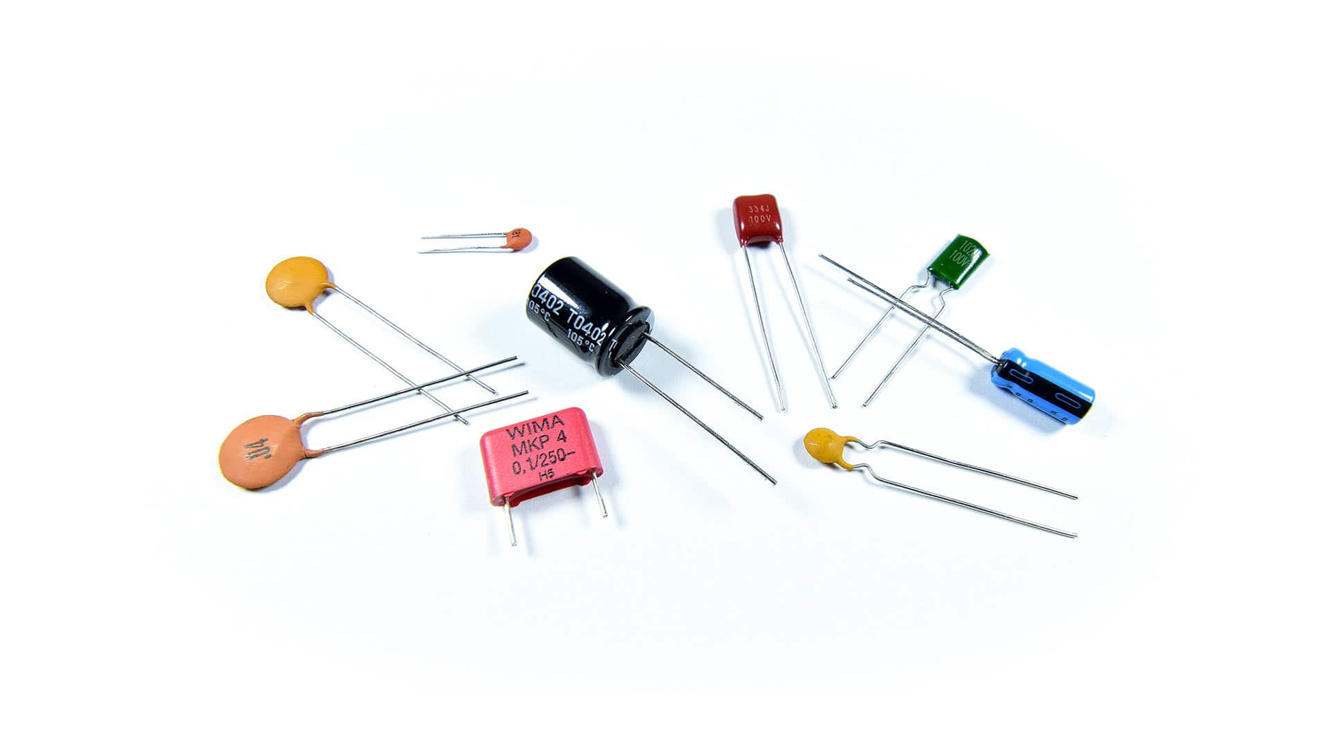
There are two main types of crossovers: passive and active. For DIY IEMs, we're focusing on passive crossovers, which are built using resistors, capacitors, and inductors. These are placed between the audio source and the drivers themselves - no external power needed.
Active crossovers, on the other hand, split the signal electronically before amplification and require their own power source. They offer more flexibility and precision but add complexity, cost, and size - things that don't play well with the tiny form factor of IEMs.
For our purposes, passive crossovers are the sweet spot: simple, reliable, and small enough to fit inside an IEM shell.
Basic Crossover Components
Passive crossovers use three main components to filter frequencies:
Capacitors (High-Pass Filters)
Capacitors block low frequencies and allow high frequencies to pass through. The larger the capacitor value (measured in microfarads, µF), the lower the frequency it will start blocking.
In crossover terms, capacitors are used to create high-pass filters - they "pass" the highs and block the lows. This is what you'd use to send only the treble to your tweeters while keeping the bass away from them.
How it works: Capacitors have a property called capacitive reactance (Xc), which is essentially their "resistance" to AC signals. The key is that this reactance is inversely proportional to frequency: Xc = 1 / (2πfC). As frequency increases, the denominator gets larger, so the reactance gets smaller - meaning high frequencies face less opposition and pass through easily, while low frequencies face high opposition and get blocked.
Additional Info: In terms of wave behavior, a capacitor stores energy in an electric field between its plates. For low-frequency waves (slow oscillations), the capacitor has time to fully charge and discharge, effectively blocking the signal. For high-frequency waves (fast oscillations), the capacitor can't keep up and acts almost like a wire, letting the signal pass. For a deeper dive into capacitive reactance and AC circuit behavior, see [[Capacitor - Wikipedia](https://en.wikipedia.org/wiki/Capacitor#AC_circuits)](https://en.wikipedia.org/wiki/Capacitor#AC_circuits).
Inductors (Low-Pass Filters)

Inductors do the opposite of capacitors - they block high frequencies and allow low frequencies to pass. The larger the inductor value (measured in millihenries, mH), the lower the frequency it will start blocking the highs.
Inductors create low-pass filters - they "pass" the lows and block the highs. This is what you'd use to send only the bass to your woofers while keeping the treble away.
How it works: Inductors have inductive reactance (XL), which increases with frequency: XL = 2πfL. As frequency goes up, the reactance gets higher - meaning high frequencies face more opposition and get blocked, while low frequencies face minimal opposition and pass through.
Additional Info: An inductor stores energy in a magnetic field created by current flowing through its coil. For high-frequency waves, the rapidly changing current creates a strong back-EMF (electromotive force) that opposes the change, blocking the signal. For low-frequency waves, the changes are slow enough that the inductor doesn't generate much opposition. For more on inductive behavior, see [[Inductor - Wikipedia](https://en.wikipedia.org/wiki/Inductor#Reactance)](https://en.wikipedia.org/wiki/Inductor#Reactance).
Important note: Inductors are chunky. Like, physically large and heavy - not great for IEMs where space is at a premium. For this reason, many IEM builders avoid inductors entirely and rely on capacitors and resistors to do the heavy lifting. We'll talk about inductor-less designs later.
Resistors (Attenuation and Damping)

Resistors don't filter frequencies - they reduce volume evenly across all frequencies. They're used for two main purposes in crossovers:
-
Level matching: If one driver is way louder than another (like a super-efficient BA tweeter paired with a quieter dynamic woofer), you can use a resistor to bring the louder driver down to match.
-
Damping: Drivers have resonances - frequencies where they naturally want to ring out and get louder than they should. A resistor placed in parallel with a driver can "damp" these resonances, smoothing out peaks and making the response more even.
How it works: Resistors simply convert electrical energy into heat, reducing the signal strength. Unlike capacitors and inductors, their resistance doesn't change with frequency - they're the straightforward "volume knob" of the crossover world.
Filter Orders and Slope
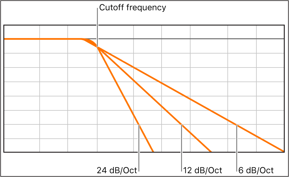
When you're designing a crossover, one of the key decisions is how aggressively you want to filter frequencies. This is described by the filter order, which determines the slope of the filter - how quickly it cuts off unwanted frequencies.
First-Order Filters (6 dB/octave)
A first-order filter uses just one component: a single capacitor for a high-pass or a single inductor for a low-pass. It has a gentle slope of 6 dB per octave, meaning that for every doubling of frequency (one octave), the volume drops by 6 dB.
Additional Info: Every filter introduces a phase shift - a time delay between the input signal and output signal. First-order filters introduce a maximum of 90° phase shift at the crossover frequency, which is relatively minimal. Higher-order filters introduce more phase shift (180° for second-order, 270° for third-order, etc.). When two drivers are producing the same frequency but out of phase, they can partially or completely cancel each other out, creating notches in the frequency response. This is why simpler crossovers often sound more "coherent" - less phase weirdness. For more on phase in AC circuits, see [[Phase (waves) - Wikipedia](https://en.wikipedia.org/wiki/Phase_(waves))](https://en.wikipedia.org/wiki/Phase_(waves)).
Pros: Simple, minimal phase shift, natural sound. Cons: Lots of frequency overlap between drivers, which can cause phase issues if not carefully managed.
Second-Order Filters (12 dB/octave)
A second-order filter uses two components: typically a capacitor and an inductor (or resistor in some designs). It has a steeper slope of 12 dB per octave, cutting off unwanted frequencies more aggressively.
Pros: Less overlap between drivers, cleaner separation. Cons: More phase shift, slightly more complex to design.
Higher-Order Filters (18+ dB/octave)
Third-order and beyond use three or more components and get progressively steeper. While these offer excellent separation, they also introduce more phase shift and require more space - not ideal for IEMs.
For most DIY IEM builds, you'll be working with first- or second-order filters. They strike a good balance between simplicity, size, and performance.
Crossover Frequency (Crossover Point)
The crossover frequency is where one driver hands off to another. For example, if you set your crossover point at 2 kHz, your woofer will handle everything below 2 kHz, and your tweeter will handle everything above it.
Choosing the right crossover frequency depends on a few factors:
-
Driver capabilities: Look at the frequency response graphs of your drivers. Where do they start to struggle? Where do they overlap comfortably? Your crossover point should be in a range where both drivers can operate reasonably well.
-
Avoiding resonances: If a driver has a big resonance peak at, say, 3 kHz, you probably don't want to cross over right at 3 kHz - that peak will bleed through and cause harshness. Cross over before or after the problem area.
-
Natural transition: The human ear is most sensitive to midrange frequencies (roughly 1-4 kHz). If your crossover point falls in this range, any phase issues or level mismatches will be very noticeable. Try to keep crossovers out of this "danger zone" if possible, or be extra careful with your design.
Impedance and Crossover Design
Here's something that trips up a lot of beginners: driver impedance directly affects how your crossover behaves.
When you calculate crossover component values, you need to know the impedance of your driver (usually measured in ohms, Ω). Most IEM drivers range from 4Ω to 32Ω, with BA drivers often sitting around 8-16Ω and dynamic drivers ranging more widely.
Why It Matters
The cutoff frequency of a filter is determined by the component value AND the driver impedance. The formula for a simple first-order high-pass filter (capacitor in series) is:
f = 1 / (2π × R × C)
Where:
- f = cutoff frequency (Hz)
- R = driver impedance (Ω)
- C = capacitor value (farads)
If your driver is 8Ω and you want a 2 kHz crossover, you'd need a capacitor of about 10 µF. But if your driver is 16Ω, that same 10 µF cap would give you a 1 kHz crossover instead - way off target.
Impedance Isn't Always Constant
Here's the annoying part: driver impedance isn't a single fixed number. It changes with frequency, often spiking dramatically at resonances. A driver rated at 8Ω nominal might actually be 6Ω at 500 Hz, 12Ω at 2 kHz, and 30Ω at its resonance peak.
This is where those .zma files mentioned in the Driver Selection guide come in handy. They show you the impedance curve across the frequency range, which helps you design a crossover that actually works as intended. If you don't have impedance data, you'll need to measure it yourself or make educated guesses and be prepared to tweak.
Common Crossover Topologies

Now that we've covered the basics, let's look at some common crossover designs you'll encounter in IEM building.
Series High-Pass (Capacitor in Series)
The simplest crossover: a capacitor placed in series with a driver (signal goes through the capacitor before reaching the driver). This blocks low frequencies and passes highs - perfect for tweeters.
When to use: When you want to protect a tweeter from bass or create a simple two-way crossover.
Parallel Low-Pass (Capacitor in Parallel)
A capacitor placed in parallel with a driver (one leg to the signal, one leg to ground). At high frequencies, the capacitor acts like a short circuit to ground, shunting those frequencies away from the driver. Low frequencies can't pass through the cap easily, so they go to the driver instead.
When to use: When you want to roll off the highs on a woofer or mid driver without using an inductor.
Zobel Network (RC Circuit)
Sometimes called an impedance compensation network, this is a resistor and capacitor in series, placed in parallel with the driver. It's used to flatten out impedance peaks and smooth the driver's response.
Additional Info: Every driver has a natural resonant frequency where the mechanical system (diaphragm, voice coil, suspension) wants to oscillate on its own. At this frequency, the driver's impedance spikes dramatically because the mechanical energy and electrical energy are fighting each other. This creates a peak in the frequency response - often unpleasant and sharp-sounding. A Zobel network provides a parallel path for these resonant frequencies to dissipate as heat, effectively damping the resonance. For more on mechanical resonance in drivers, see [[Resonance - Wikipedia](https://en.wikipedia.org/wiki/Resonance)](https://en.wikipedia.org/wiki/Resonance).
When to use: When a driver has a nasty resonance peak that's causing problems, or when you need to stabilize the impedance for the crossover to work properly.
Notch Filter (Parallel RC to Ground)
A resistor and capacitor in parallel to ground, tuned to create a deep notch at a specific problem frequency. This is a surgical tool for taming a particularly bad resonance.
When to use: When you have a sharp, annoying peak that you need to kill without affecting the rest of the frequency range too much.
Full Band-Pass (Series + Parallel Filters)
Combines a high-pass filter (series capacitor) and a low-pass filter (parallel capacitor or inductor) to create a "band-pass" - the driver only gets a specific slice of the frequency spectrum.
When to use: For midrange drivers in a three-way or more complex crossover, where you want to keep both the bass and treble away.
Inductor-Less Crossover Design
As mentioned earlier, inductors are bulky and not ideal for IEMs. Luckily, you can design effective crossovers using only capacitors and resistors - often called RC crossovers.
The trade-off is that you lose some efficiency (resistors dissipate energy as heat) and you have less control over the exact filter shape. But for IEMs, where drivers are close to your eardrum and don't need much power anyway, the efficiency loss is negligible. The space savings are well worth it.
Design Thinking: Building Toward a Target Sound Signature

Let's walk through the thought process of designing a crossover for a specific goal. We'll use the Harman Target Curve as our example - a scientifically researched frequency response that most listeners find pleasing for in-ear monitors.
What is the Harman Target?
The Harman Target is a frequency response curve developed by Harman International (now owned by Samsung) through extensive blind listening tests with trained and untrained listeners. The key characteristics are:
- Elevated bass (roughly +5-8 dB from 20-200 Hz) for warmth and impact
- Slightly elevated lower mids (around 200-500 Hz) for body and fullness
- Neutral midrange (500 Hz - 2 kHz) for natural vocal reproduction
- Presence boost (around 3 kHz, +10 dB) for clarity and detail
- Gentle treble roll-off (above 10 kHz) to avoid harshness
Our Starting Point: Driver Selection
For this example, let's say we're building a three-way hybrid IEM with:
- 1x Dynamic Driver (10mm): Rated 6Ω, excellent bass response (20 Hz - 2 kHz capable), has a resonance peak at 1.8 kHz
- 1x Balanced Armature (mid): Rated 12Ω, clean midrange (300 Hz - 8 kHz capable), has a peak at 2.5 kHz
- 1x Balanced Armature (treble): Rated 8Ω, detailed highs (2 kHz - 18 kHz capable), has peaks at 6 kHz and 10 kHz
Step 1: Determining Crossover Points
Looking at our target and driver capabilities:
Bass-to-Mid Crossover (~500-800 Hz):
- The Harman target wants elevated bass below 200 Hz, then a natural transition through the mids
- Our DD can handle up to 2 kHz but has a resonance at 1.8 kHz that we need to suppress
- Our mid BA can go down to 300 Hz comfortably
- Decision: Cross over around 600-700 Hz with the DD handling everything below, and use a parallel capacitor to kill the DD's 1.8 kHz resonance
Mid-to-Treble Crossover (~4-5 kHz):
- The Harman target wants the 3 kHz presence peak in the mids
- Our mid BA has good response up to 8 kHz but with a peak at 2.5 kHz
- Our treble BA can start as low as 2 kHz but shines above 5 kHz
- Decision: Cross over around 5 kHz, letting the mid BA handle the critical 2-4 kHz range (where our ears are most sensitive), while the treble BA takes over for air and sparkle
Step 2: Designing the Bass Path (DD)
Goals:
- Preserve strong bass response (20-200 Hz)
- Roll off starting around 700 Hz to prevent midrange bleed
- Aggressively suppress the 1.8 kHz resonance peak
- Match level with the other drivers (DD is typically louder)
Crossover design:
- Series resistor (15-22Ω): Attenuates the overall output of the sensitive DD to match the quieter BAs. This also provides some damping for the resonance.
- Parallel capacitor (4.7µF): Creates a low-pass filter with the driver's 6Ω impedance. Using f = 1/(2π × R × C), this gives us approximately 5.6 kHz cutoff, but more importantly, it creates a strong attenuation at the 1.8 kHz resonance. The cap shunts high frequencies to ground, cleaning up the DD's response.
Why this works: The series resistor is like turning down the volume knob on the DD, while the parallel capacitor acts as an "escape route" for unwanted high frequencies, sending them to ground instead of to your ear.
Step 3: Designing the Mid Path (BA)
Goals:
- Block bass below 600 Hz (protect the small BA from overexcursion)
- Let the critical midrange (600 Hz - 5 kHz) through naturally
- Start rolling off above 5 kHz to hand off to the treble driver
- Tame the 2.5 kHz peak without losing the Harman presence region
Crossover design:
- Series capacitor (10µF): High-pass filter to block bass. With the 12Ω BA impedance, this gives us f = 1/(2π × 12Ω × 10µF) ≈ 1.3 kHz. Wait - that's higher than our 600 Hz target! This is where impedance variation comes in. At lower frequencies, the BA's impedance is higher (maybe 16-20Ω), which lowers the effective cutoff closer to 600-800 Hz.
- Series resistor (10-15Ω): Provides level matching and light damping for the 2.5 kHz peak without overdoing it (we want some presence boost for Harman).
- Parallel capacitor (2.2µF): Creates a gentle low-pass above 5 kHz. With the combined impedance of the resistor and driver (roughly 22-27Ω), this gives us f ≈ 6 kHz, perfect for handing off to the treble.
Why this works: The series capacitor is a "bass bouncer" - it won't let low frequencies through. The series resistor fine-tunes the volume and response, while the parallel capacitor starts gently rolling off the highs so the transition to the treble driver is smooth.
Step 4: Designing the Treble Path (BA)
Goals:
- Block everything below 5 kHz
- Deliver clean, extended treble (5-18 kHz)
- Smooth out the peaks at 6 kHz and 10 kHz
- Match the gentle roll-off in the Harman target above 10 kHz
Crossover design:
- Series capacitor (2.2µF): High-pass filter to block mids and bass. With 8Ω impedance, this gives f = 1/(2π × 8Ω × 2.2µF) ≈ 9 kHz. But again, impedance variation means the effective cutoff will be lower, around 5-6 kHz where we want it.
- Parallel resistor (22-33Ω): Light damping to smooth the 6 kHz and 10 kHz peaks without killing the air and extension. Higher values mean less damping (more natural response), lower values mean more control (smoother but potentially duller).
Why this works: The series cap ensures only treble reaches this delicate driver, while the parallel resistor acts like a gentle hand on the reins - it prevents the driver from getting too excited at its resonance peaks while still letting it sing.
Step 5: The Complete Picture
When you combine all three paths, you get:
- Strong, controlled bass from the DD without midrange bleed
- Clear, detailed midrange from the mid BA with proper presence boost
- Smooth, extended treble from the treble BA without harshness
The crossover points create smooth transitions, and each driver operates in its comfort zone. The resistors fine-tune the levels so nothing dominates, and the capacitors ensure frequencies go where they should.
This is the fundamental thinking behind crossover design: identify your target → understand your drivers → design filters to bridge the gap. The math gives you starting points, but listening and iteration refine it into something that actually sounds good.
Key insight: Real-world crossover design is about problem-solving. Every driver has quirks (resonances, roll-offs, sensitivity differences), and your crossover is the toolbox you use to smooth them out and steer toward your target sound signature. There's rarely a "perfect" solution on paper - you iterate, listen, measure, and adjust until it sounds right.
Understanding Frequency Division
When you're designing a multi-driver IEM, you're essentially dividing up the audible frequency spectrum (roughly 20 Hz to 20 kHz) among your drivers. Each driver gets a "slice" of the spectrum to handle.
Common Frequency Divisions in Real IEMs
Let's look at how different IEMs across various price points handle frequency division. Note that the specific crossover frequencies and configurations below are estimates based on driver specifications, frequency response measurements, and community analysis, as manufacturers rarely disclose exact crossover designs. These examples illustrate common approaches to frequency division rather than exact specifications:
Budget Two-Way Split ($20-100) - KZ ZSN Pro X style (1DD + 1BA):
- Dynamic Driver: 20 Hz - 1.5 kHz (bass and lower mids)
- Balanced Armature: 1.5 kHz - 20 kHz (upper mids and treble)
- Crossover point: Around 1.5-2 kHz
- Design logic: A single DD handles the bass where it excels, while a single BA covers everything else. The crossover point is chosen below the ear's most sensitive range (2-4 kHz) to minimize any phase issues that might be audible.
Mid-Range Three-Way Split ($300-500) - Moondrop Blessing 2/3 approach (Multi-BA):
- Low-frequency BA cluster: 20 Hz - 800 Hz (bass)
- Mid-frequency BA cluster: 800 Hz - 6 kHz (mids)
- High-frequency BA cluster: 6 kHz - 20 kHz (treble)
- Crossover points: Around 800 Hz and 6 kHz
- Design logic: Multiple BAs allow for more precise frequency control. The lower crossover at 800 Hz keeps bass isolated, while the higher crossover at 6 kHz ensures the mid drivers handle the critical vocal range without interference.
High-End Hybrid Split ($1000+) - Hisenior Mega5-EST approach (1DD + 2BA + 2EST):
- Dynamic Driver: 20 Hz - 500 Hz (sub-bass and bass)
- Balanced Armature (x2): 500 Hz - 5 kHz (mids, possibly split further)
- Electrostatic (x2): 5 kHz - 20 kHz (treble and ultra-high extension)
- Crossover points: Around 500 Hz and 5 kHz
- Design logic: Each driver type does what it does best. DD for impactful bass, BAs for detailed and efficient mids, and ESTs for ultra-clean treble extension with minimal distortion. The EST crossover is placed high (5 kHz+) to leverage their strength in the ultra-highs where other drivers struggle.
Single-Driver Designs - Moondrop Aria, 7Hz Timeless:
- Full-range driver: 20 Hz - 20 kHz (everything)
- No crossover needed
- Design logic: High-quality single drivers can cover the full spectrum without crossovers, eliminating phase issues entirely. However, they may not excel in every frequency range the way specialized multi-driver setups can.
These divisions aren't arbitrary - they're chosen based on the physical capabilities of each driver type, the target sound signature, and avoiding problematic frequency ranges where our ears are most sensitive to imperfections.
The Goal of Frequency Division
The goal is to make sure each driver is working in its sweet spot - the frequency range where it sounds best and has the flattest response. By dividing frequencies intelligently, you can:
- Get better overall sound quality (each driver doing what it does best)
- Reduce distortion (drivers not struggling outside their comfort zone)
- Increase efficiency (drivers working where they're most efficient)
- Protect delicate drivers (tweeters not getting blasted with bass)
In the next sections (Component Picking, PCB Design, and Tuning with VituixCAD), we'll dive into the practical side of taking these concepts and turning them into real, working crossovers that sound great.
Citations & Further Reading
-
"Audio crossover," Wikipedia, https://en.wikipedia.org/wiki/Audio_crossover (accessed Nov. 10, 2025).
-
"Electronic filter," Wikipedia, https://en.wikipedia.org/wiki/Electronic_filter (accessed Nov. 10, 2025).
-
"Capacitor," Wikipedia, https://en.wikipedia.org/wiki/Capacitor#AC_circuits (accessed Nov. 10, 2025).
-
"Inductor," Wikipedia, https://en.wikipedia.org/wiki/Inductor#Reactance (accessed Nov. 10, 2025).
-
"Phase (waves)," Wikipedia, https://en.wikipedia.org/wiki/Phase_(waves) (accessed Nov. 10, 2025).
-
"Resonance," Wikipedia, https://en.wikipedia.org/wiki/Resonance (accessed Nov. 10, 2025).
-
E. M. Long, "Loudspeaker crossovers and frequency response," Audio Engineering Society, https://www.aes.org/ (accessed Nov. 10, 2025).
-
R. Small, "Direct-Radiator Loudspeaker System Analysis," Journal of the Audio Engineering Society, vol. 20, no. 6, pp. 383-395, 1972.
-
S. Olive et al., "A Virtual Headphone Listening Test Methodology," Audio Engineering Society Convention 133, 2012.
-
"KZ ZSN PRO X," Head-Fi.org, https://www.head-fi.org/showcase/kz-zsn-pro-x.24613/ (accessed Nov. 10, 2025).
-
"KZ ZSN PRO X," Linsoul Audio, https://www.linsoul.com/products/kz-zsn-pro-x (accessed Nov. 10, 2025).
-
"Moondrop Blessing 2," Head-Fi.org, https://www.head-fi.org/showcase/moondrop-blessing-2.24140/ (accessed Nov. 10, 2025).
-
"MOONDROP BLESSING2 1DD+4BA In-Ear Monitor," MOONDROP Official Website, https://moondroplab.com/en/products/blessing2 (accessed Nov. 10, 2025).
-
"Mega5-EST 5-Drivers Hybrid IEM (Universal)," hisenior, https://www.hisenior-iem.com/products/mega5est-hybrid-iem (accessed Nov. 10, 2025).
-
"Hisenior Mega5-EST," Headfonia, https://www.headfonia.com/hisenior-mega5est-review/ (accessed Nov. 10, 2025).
-
"MOONDROP ARIA In-Ear Monitor," MOONDROP Official Website, https://moondroplab.com/en/products/aria (accessed Nov. 10, 2025).
-
"Moondrop Aria 2021," Head-Fi.org, https://www.head-fi.org/showcase/moondrop-aria-2021.25077/reviews (accessed Nov. 10, 2025).
-
"7HZ Timeless 14.2mm Planar HiFi In-ear Earphone," Linsoul Audio, https://www.linsoul.com/products/7hz-timeless (accessed Nov. 10, 2025).
-
"7HZ Timeless Planar In-ear Headphone," Shenzhen Audio, https://shenzhenaudio.com/products/7hz-timeless-iems-14-2mm-planar-hifi-music-monitor-in-ear-earphones-cnc-aluminum-shell-earbuds-with-detachable-mmcx-cable (accessed Nov. 10, 2025).
20."What is a Capacitor?," Circuit Basics, https://www.circuitbasics.com/what-is-a-capacitor/ (accessed Nov. 10, 2025).
21."Inductors," CET Technology, https://cettechnology.com/inductors/ (accessed Nov. 10, 2025).
22."Resistors: An In-Depth Guide to the Electrical Component," Microchip USA, https://www.microchipusa.com/electrical-components/resistors-an-in-depth-guide-to-the-electrical-component (accessed Nov. 10, 2025).
23."Logic Pro User Guide - EQ," Apple Support, https://support.apple.com/en-am/guide/logicpro/lgsife41a2e8/mac (accessed Nov. 10, 2025).
24."Crinacle's IEM Ranking List," Head-Fi.org, https://www.head-fi.org/threads/crinacles-iem-ranking-list.857498/ (accessed Nov. 10, 2025).