Shell Design
Overview
This section covers the workflow for designing a custom IEM shell in Autodesk Fusion 360. Just like with the PCB design, we won't be doing a button-by-button tutorial of Fusion (there are plenty of those on YouTube). Instead, we will focus on the specific geometric workflow used to create ergonomic, printable shells.
For this guide, we are modeling a simpler shell designed for a single Dynamic Driver (1DD) setup. This makes it easier to understand the core concepts of lofting and shaping before tackling complex multi-driver builds.
Reference: This workflow is heavily inspired by standard surface-modeling techniques. You can see a similar workflow in action in this video tutorial.
Phase 1: The Master Sketch (2D)
Everything starts with a 2D sketch. We need to lay out the "floor plan" of the shell before we can build it up.
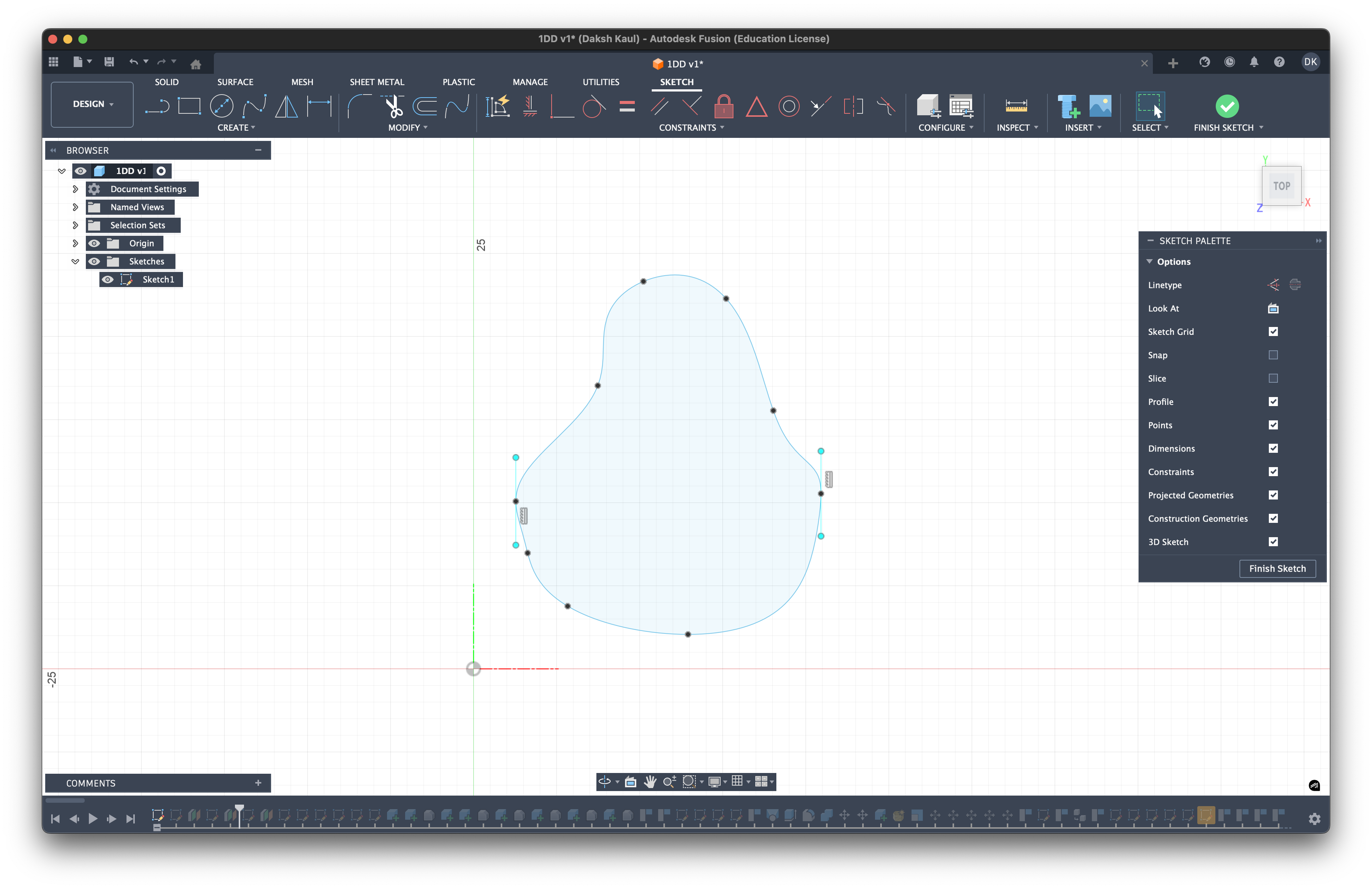
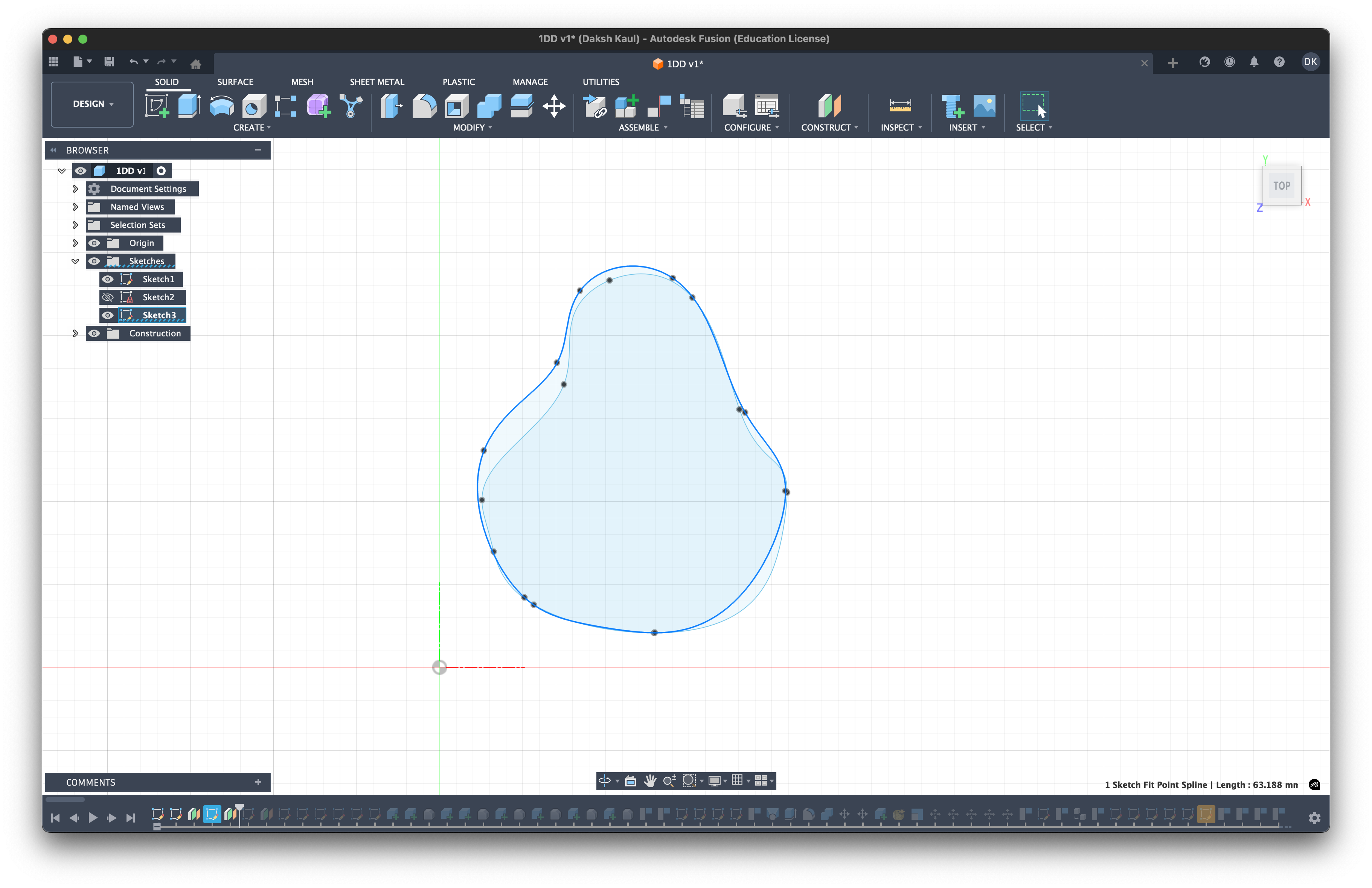
1. The Outer Contour (Faceplate)
First, we draw the outermost shape of the shell. This corresponds to the faceplate area that sits flush against your ear.
- Dimensions: For my ear fitting, I utilized a bounding box roughly 25mm x 20mm.
- Shape: Think of it as a rounded right-angled triangle. You want to contour the edges to match the concha of your ear.
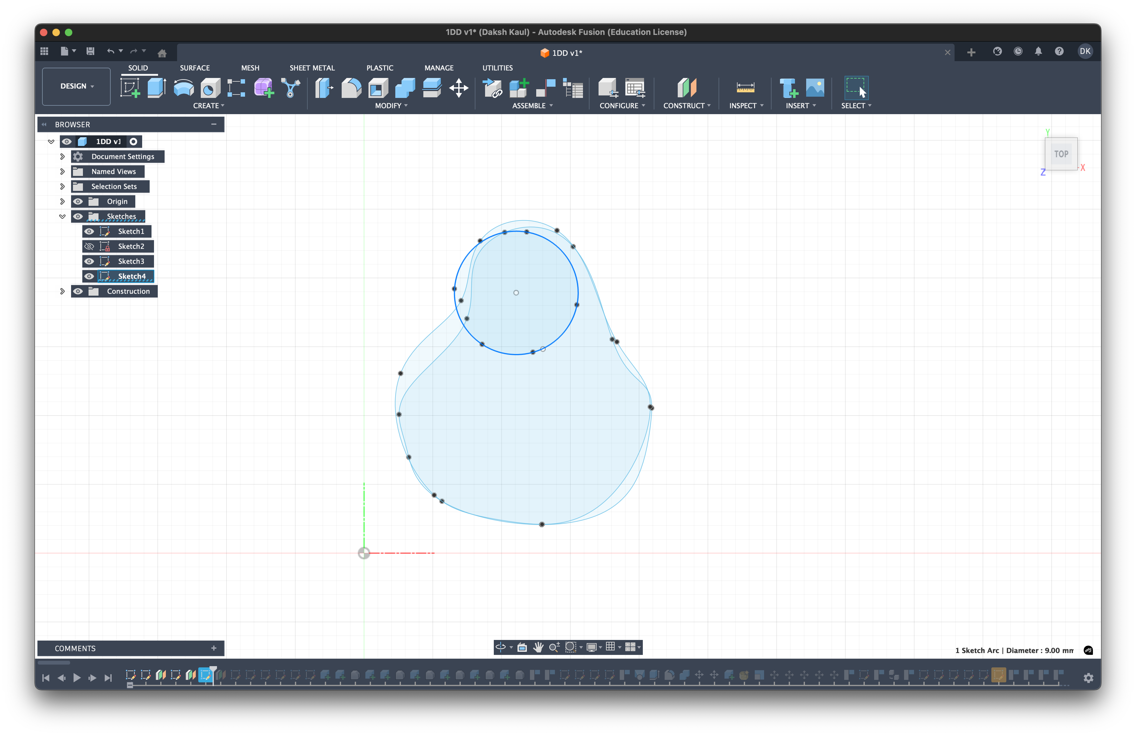
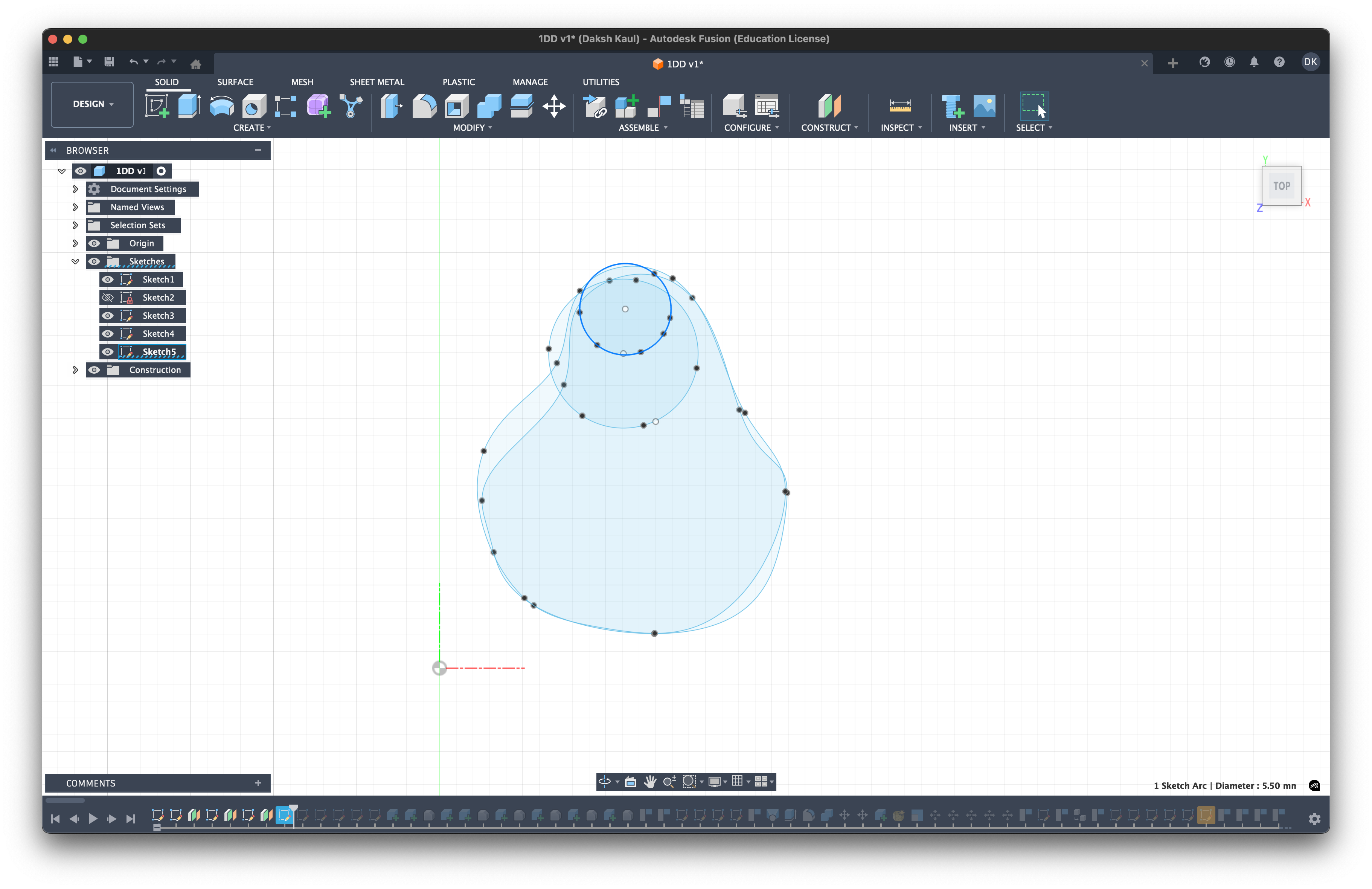
2. The Nozzle & Depth Profiles
Once the base is defined, we layer additional profiles on top of it to define the height and the nozzle.
- Nozzle Base: Draw a circle towards the top-left of the shape. This is where the nozzle starts.
- Nozzle Tip: Draw a smaller circle representing the exit of the nozzle.
- Nozzle Middle: Optional but recommended. adding a middle circle between the base and tip gives you extra control over the nozzle's taper, and allows for a curved, organic transition ("bell mouth") rather than a simple straight cone.
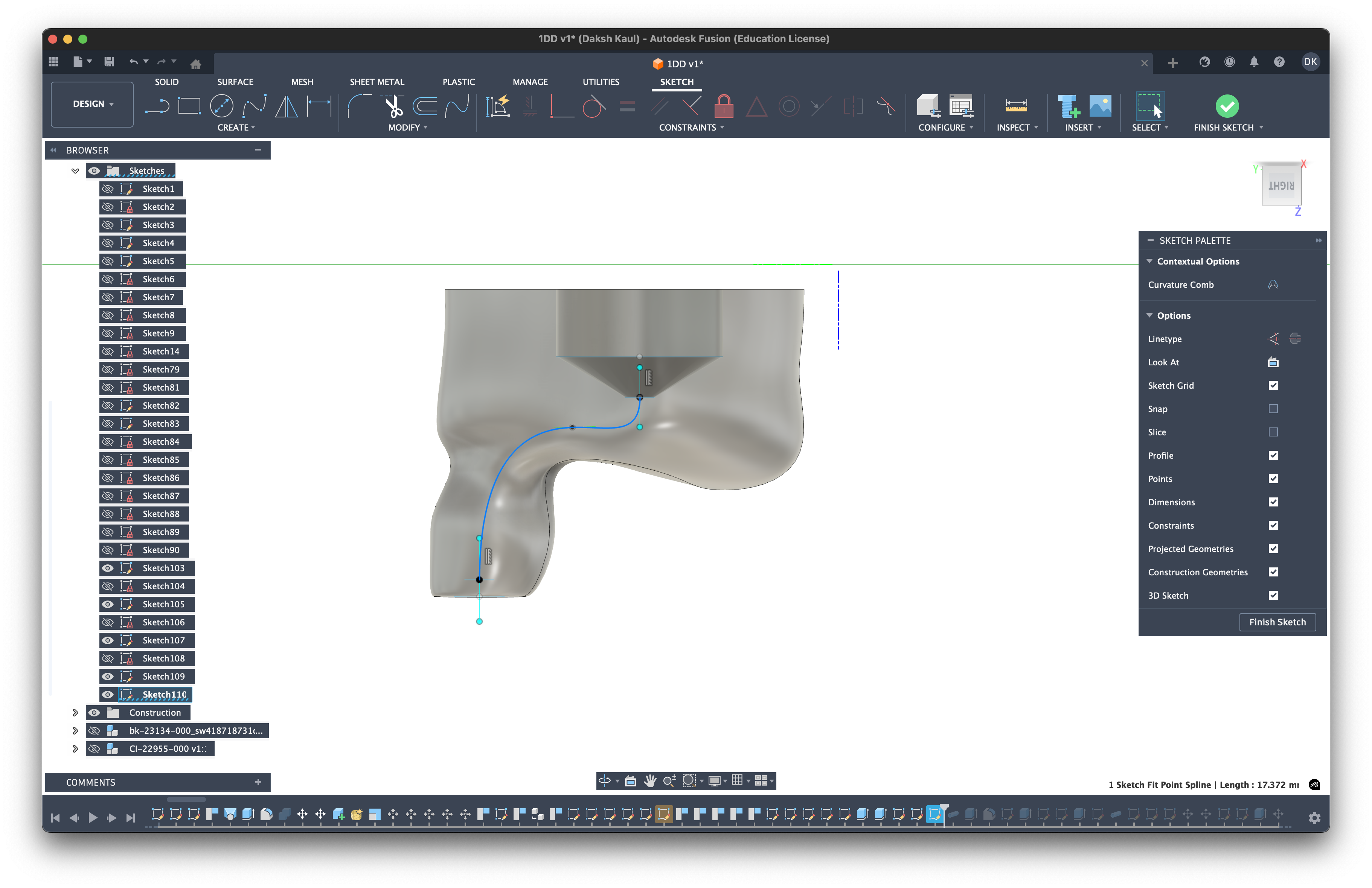
Phase 2: The Rails (3D Sketching)
Now we need to connect these flat 2D profiles in 3D space to create the "skeleton" of our shell. We call these lines Rails. We draw fitted splines that run from the points on our base contour up to the corresponding points on the nozzle. This defines how the walls of the shell will curve up from your ear to the tip.
- Base Constraints (Perpendicular): At the bottom (where the rail meets the faceplate), apply a constraint to make the line point vertically upwards (Z-direction).
- Why? This ensures the walls of the shell start perfectly straight up before curving. This prevents weird geometric twisting or "dips" near the edge and ensures a flat surface for the faceplate.
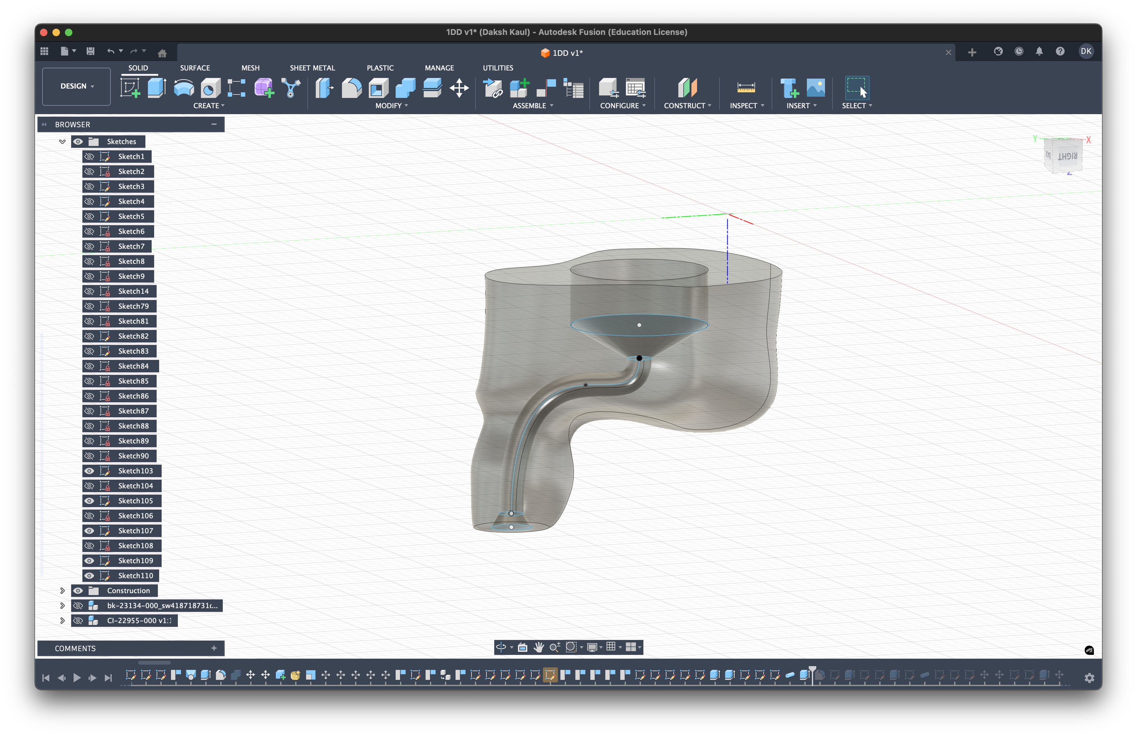
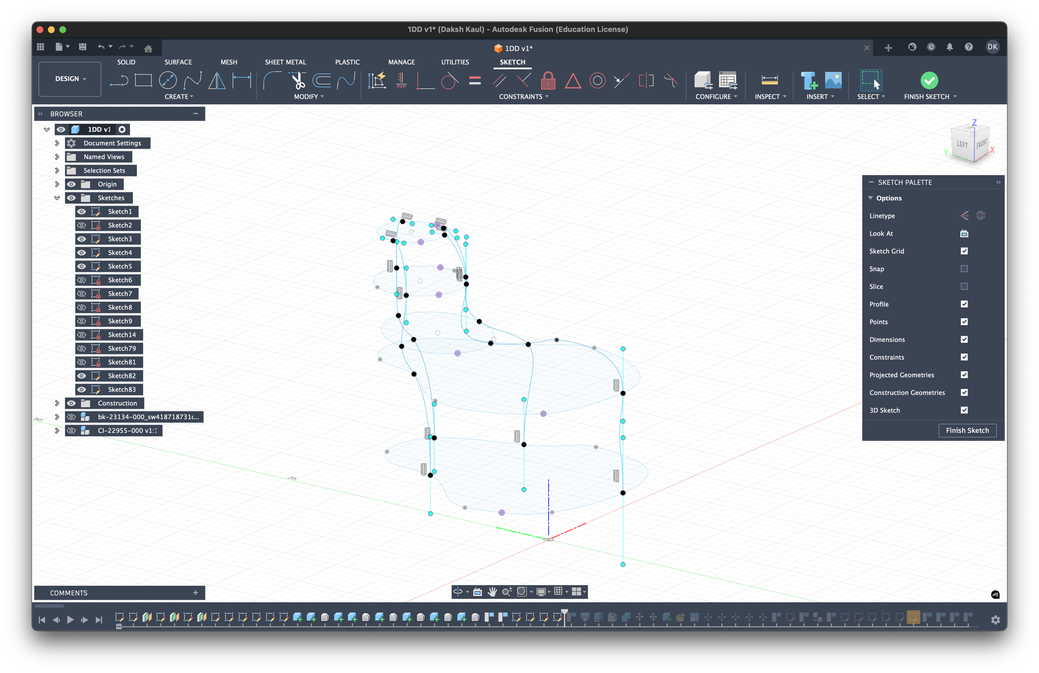 Above: Isometric view of the 3D rails connecting the base to the nozzle.
- Nozzle Constraints (Parallel/Tangent): At the top (where the rail meets the nozzle), apply constraints so the line lands flat/tangent to the nozzle ring.
- Why? This creates a curved transition into the nozzle rather than a sharp, angular one. It feels smoother in the ear and is often cleaner to 3D print because it avoids sharp resin ridges.
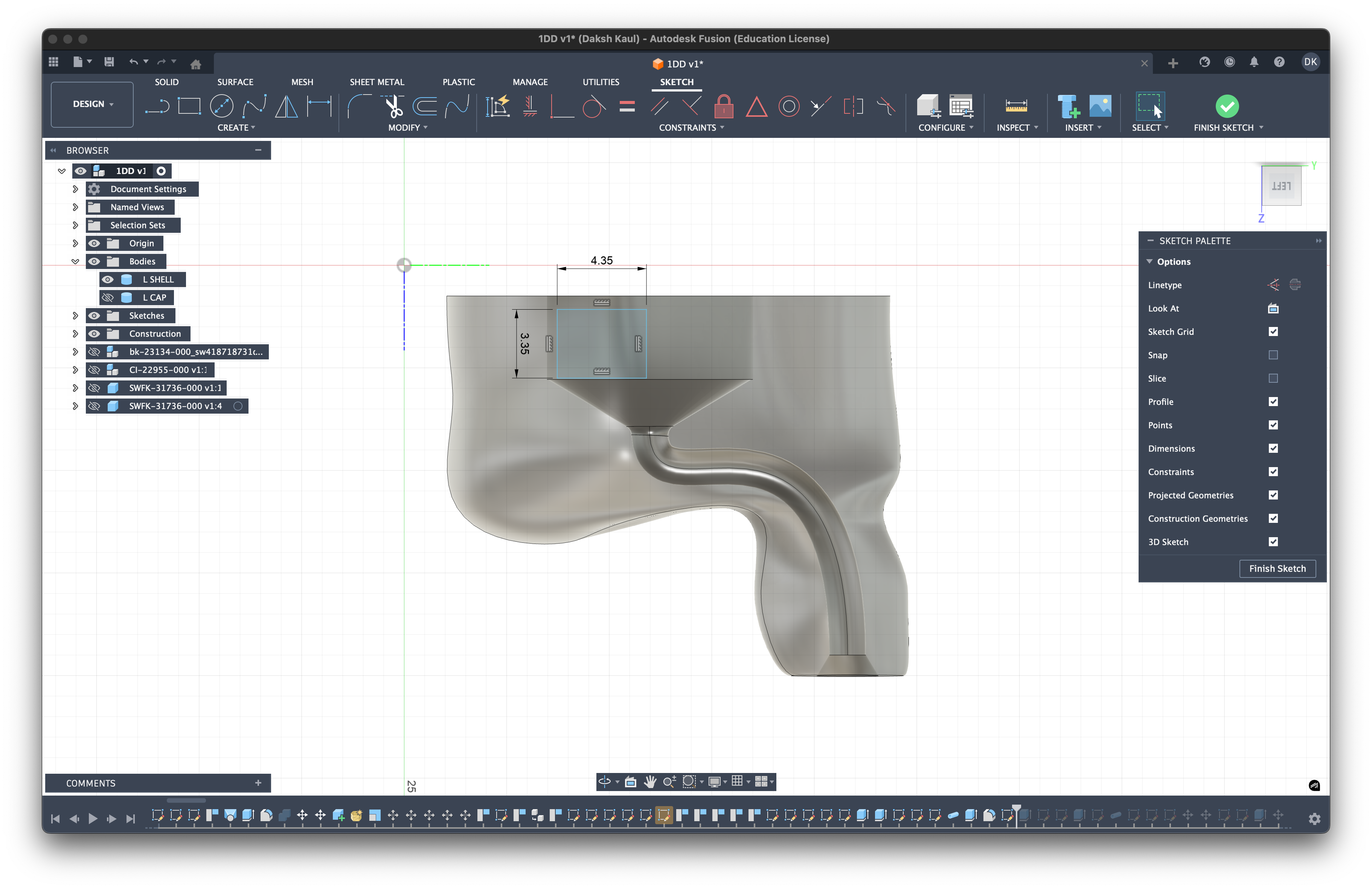
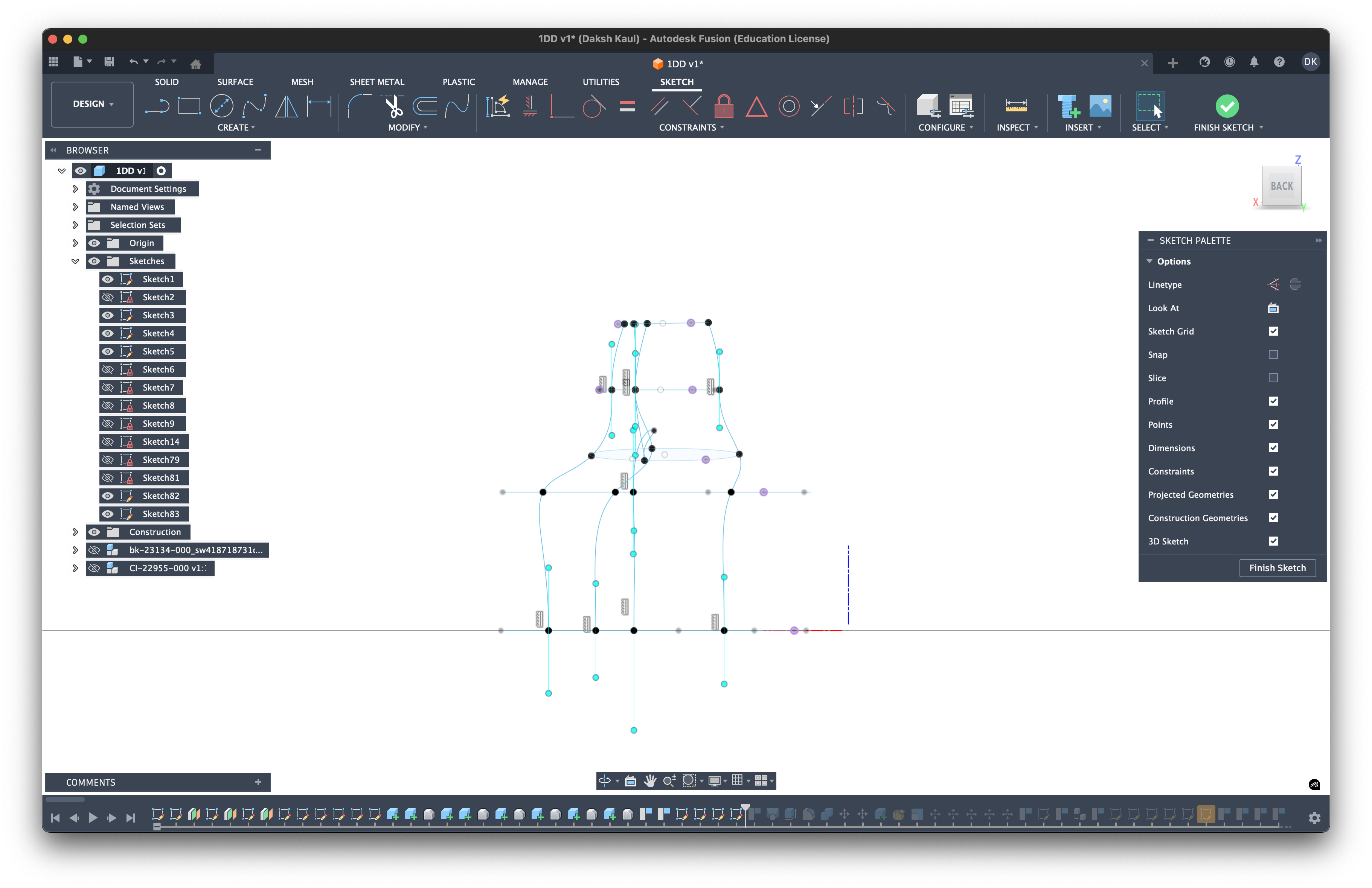 Above: Side view. Notice how the blue rail lines start vertically straight up from the bottom (left) and curve smoothly to land flat on the nozzle (right).
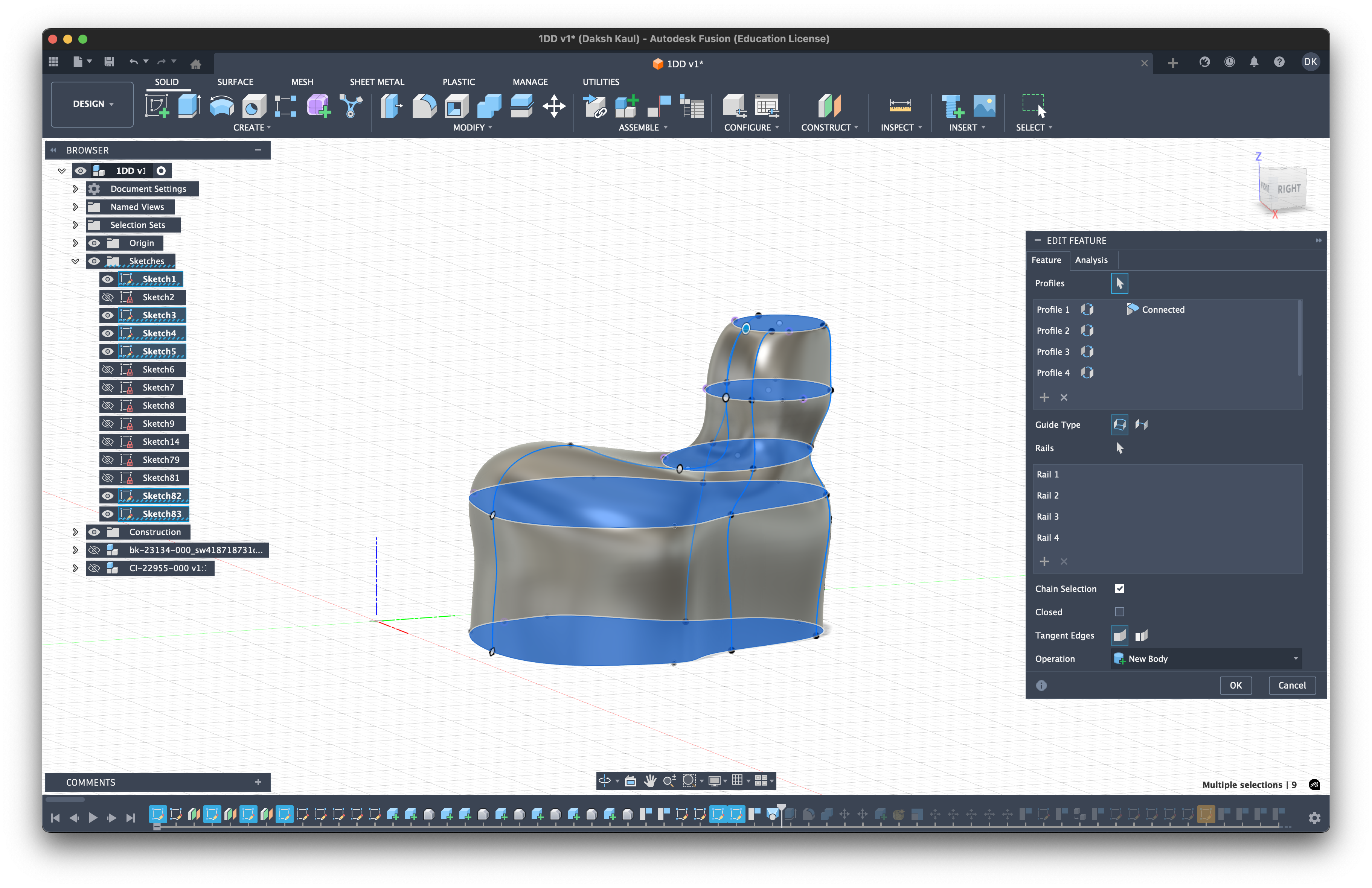
Phase 3: Lofting the Body
Once you have your 2D profiles and your 3D rails, it's time to create the solid body. We use the Loft tool for this.
- Select Profiles: In the Loft menu, select your base sketch (faceplate) as the first profile and your nozzle base sketch as the second profile.
- Select Rails: Click on the "Rails" selection box and choose the 3D spline rails you drew in Phase 2.
- Result: Fusion 360 will stretch a smooth surface between your profiles, following the exact curve of your rails. This creates the main ergonomic shape of the IEM.
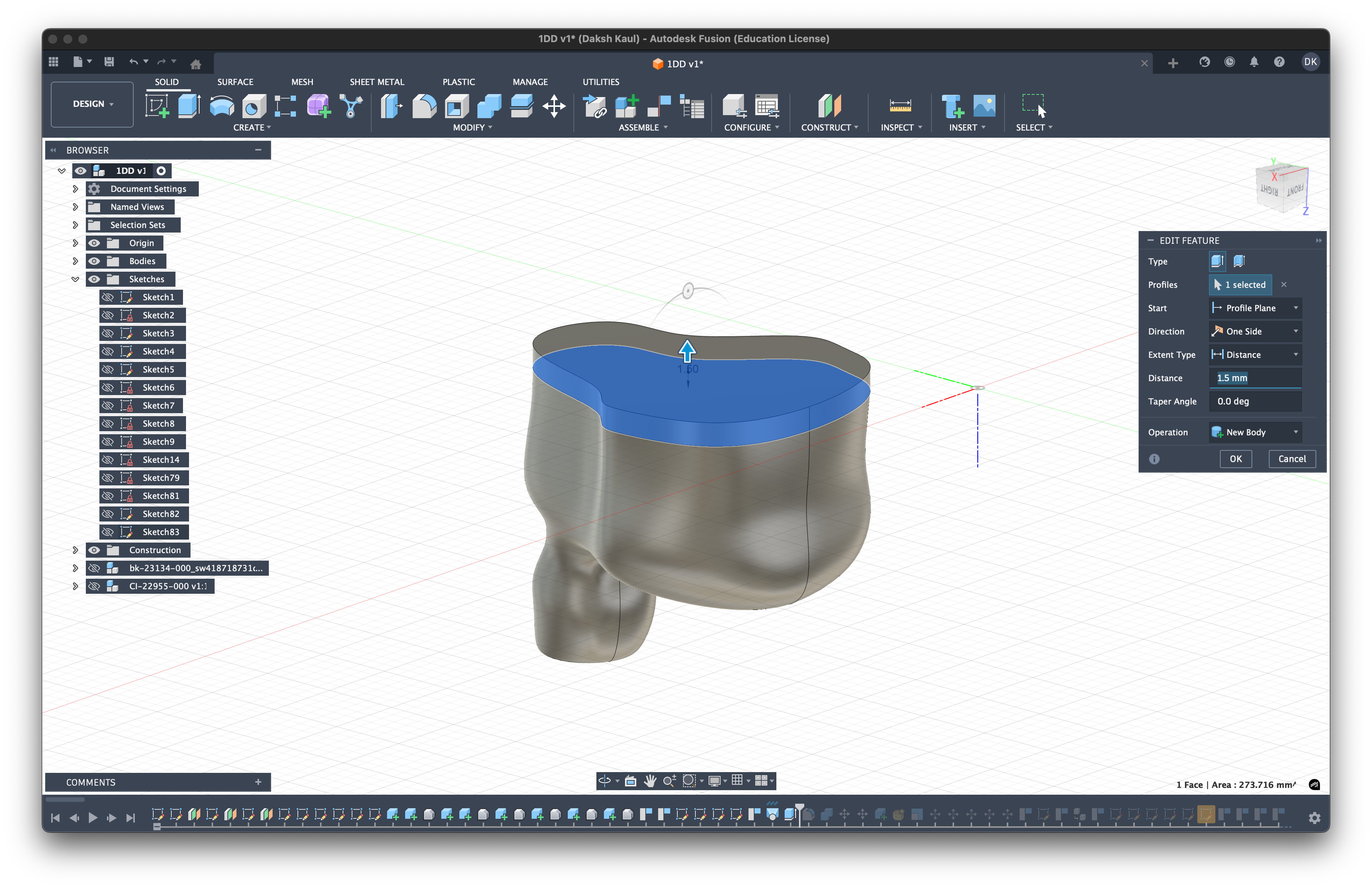
Phase 4: The Cap (Faceplate)
We need to create a separate volume for the faceplate (or "cap").
- Extrude: Select the flat bottom face of your newly lofted body.
- Distance: Extrude it downwards by 1.5mm - 2.0mm. If you have a complex crossover or bulky wiring, you might need more depth here.
- New Body: Make sure to set the operation to "New Body". This keeps the cap separate from the shell, which is critical for assembly later.
 4. Chamfer (Optional): You can add a small chamfer or fillet to the bottom edge for a smoother look and feel.
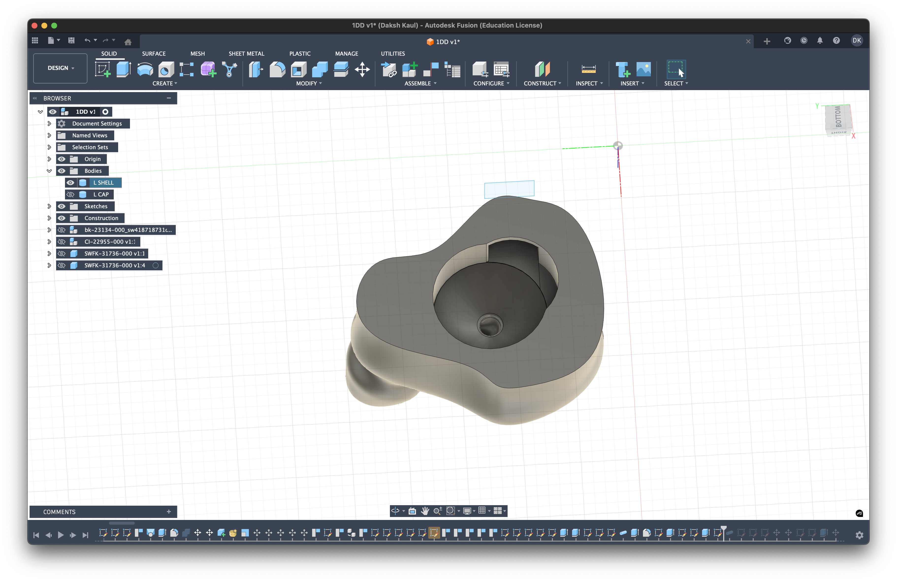
Phase 5: Creating the "Full Resin" Interior
Instead of just hollowing out the shell (making it a thin skin, aka. hollow-resin build), we are going to create a Solid Body or often times called Full Resin build. This means the shell is printed as a solid block of material with specific cavities carved out for the drivers and sound tubes.
Why do this?
- Durability: A solid shell is incredibly robust. It won't crack if dropped because there are no thin, unsupported walls.
- Acoustic Isolation: The mass of the resin dampens vibrations, reducing unwanted resonance.
- Ease of Assembly: You don't need to fiddle with tiny PVC tubes and glue. The "tubes" are printed directly into the shell.
Step 1: Carving the Driver Cavity
- Measure: Check the datasheet for your specific driver (e.g., the 10mm Dynamic Driver). Note the diameter and height.
- Create a Cut: In Fusion 360, create a cylinder or custom shape inside the shell body that matches your driver's dimensions.
- Tolerance: Add 0.05mm - 0.1mm of clearance to the diameter. Resin printing is not perfect; shrinkage or expansion can happen. You need this wiggle room so the driver fits without forcing it.
- Resin Sealing: This small gap also allows a tiny amount of UV resin to wick around the driver during assembly, acting as a glue that perfectly seals the driver in place. This prevents sound leakage, which is critical for bass response.
Step 2: Venting (Critical for Dynamic Drivers)
Dynamic drivers move air. If you seal them completely tight in a small cavity, the air pressure builds up behind the diaphragm, restricting its movement. This kills the bass response.
- The Vent: Create a small channel (0.3mm - 0.5mm) that connects the back of the driver cavity to the outside world (usually through the faceplate).
- Tuning: You can place a metal mesh or acoustic damper over this vent to fine-tune the bass quantity.
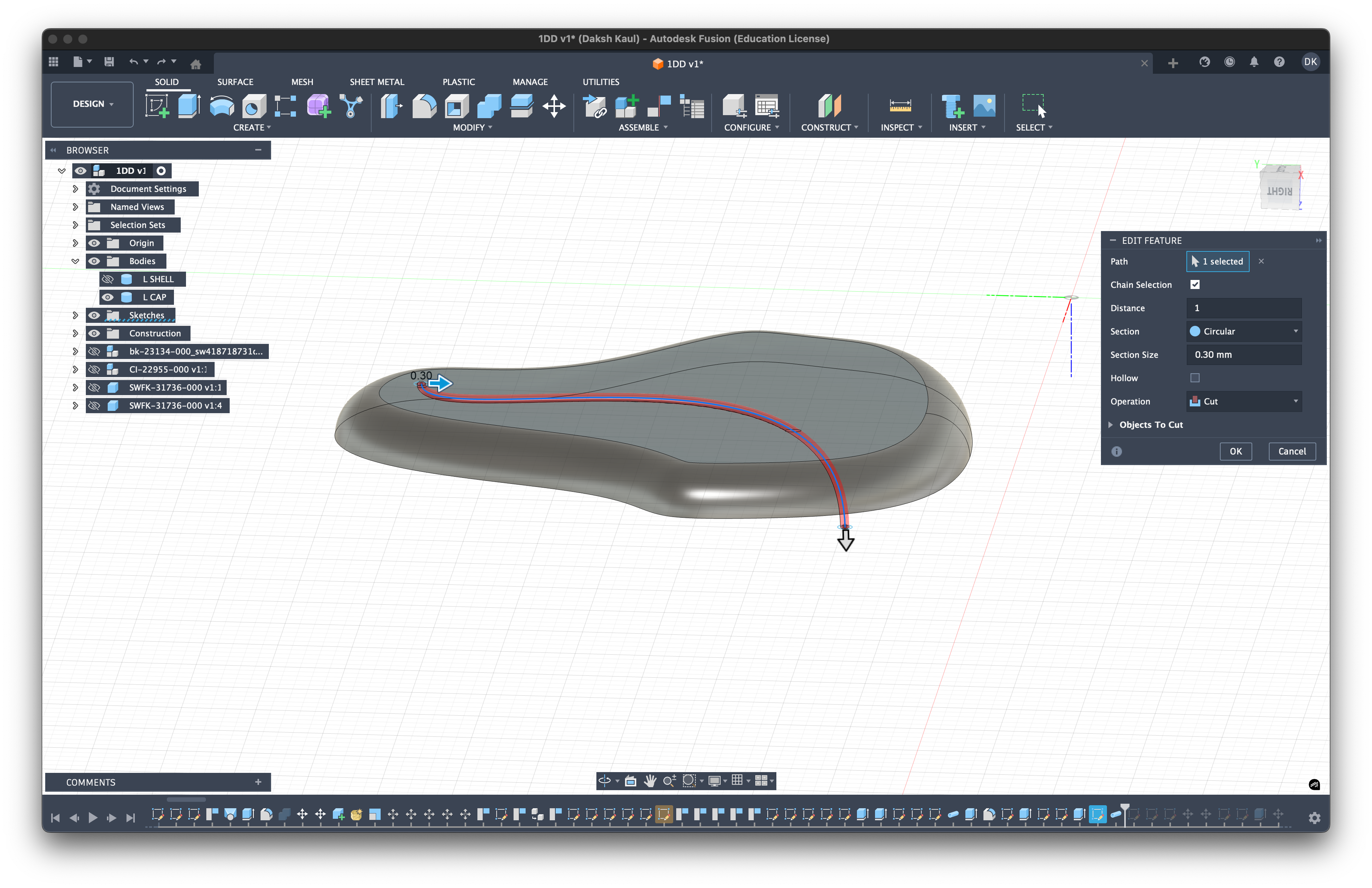
Phase 6: Acoustic Tubing & Physics
Now for the most important part: the sound tubes. Instead of using vinyl tubing, we will "cut" these tubes directly through the solid resin.
1. Creating the Path
Use the Pipe or Sweep tool. Draw a 3D spline from the output of your driver cavity to the tip of the nozzle. Then, cut a pipe along this path.
2. Tube Diameter (Acoustic Filtering)
The diameter of this tube acts as an acoustic filter.
- Narrow Tubes: act as a low-pass filter (reduce treble).
- Wide Tubes: allow more high frequencies to pass.
- Horn/Bell Mouth: Widening the tube at the exit (the nozzle tip) can improve high-frequency extension by acting as an acoustic impedance match.
3. Tube Length (Time Alignment)
The length of the tube determines when the sound reaches your ear.
- Speed of Sound: Sound travels approx. 343 m/s.
- The Problem: Different drivers react at different speeds. An Electrostatic (EST) driver is near-instant. A Dynamic Driver (DD) is heavy and "slow" (it has a delay before it starts moving).
- The Solution: If you have a fast tweeter and a slow woofer, you can make the tweeter's tube longer. This physically delays the treble so it arrives at your eardrum at the exact same moment as the bass. This is called "Time Alignment" or "Phase Alignment."
4. Helmholtz Resonators (Optional)
If you have a nasty treble peak you can't fix with the crossover, you can build a Helmholtz Resonator directly into the shell.
- What is it? A dead-end side branch off the main sound tube.
- How it works: It acts like blowing across the top of a bottle. It resonates at a specific frequency and absorbs energy at that frequency, creating a notch filter.
- Formula: f = v/(2π) × √(A/(V×L))
- f = Frequency to cut (Hz)
- v = Speed of sound
- A = Area of the neck
- V = Volume of the cavity
- L = Length of the neck
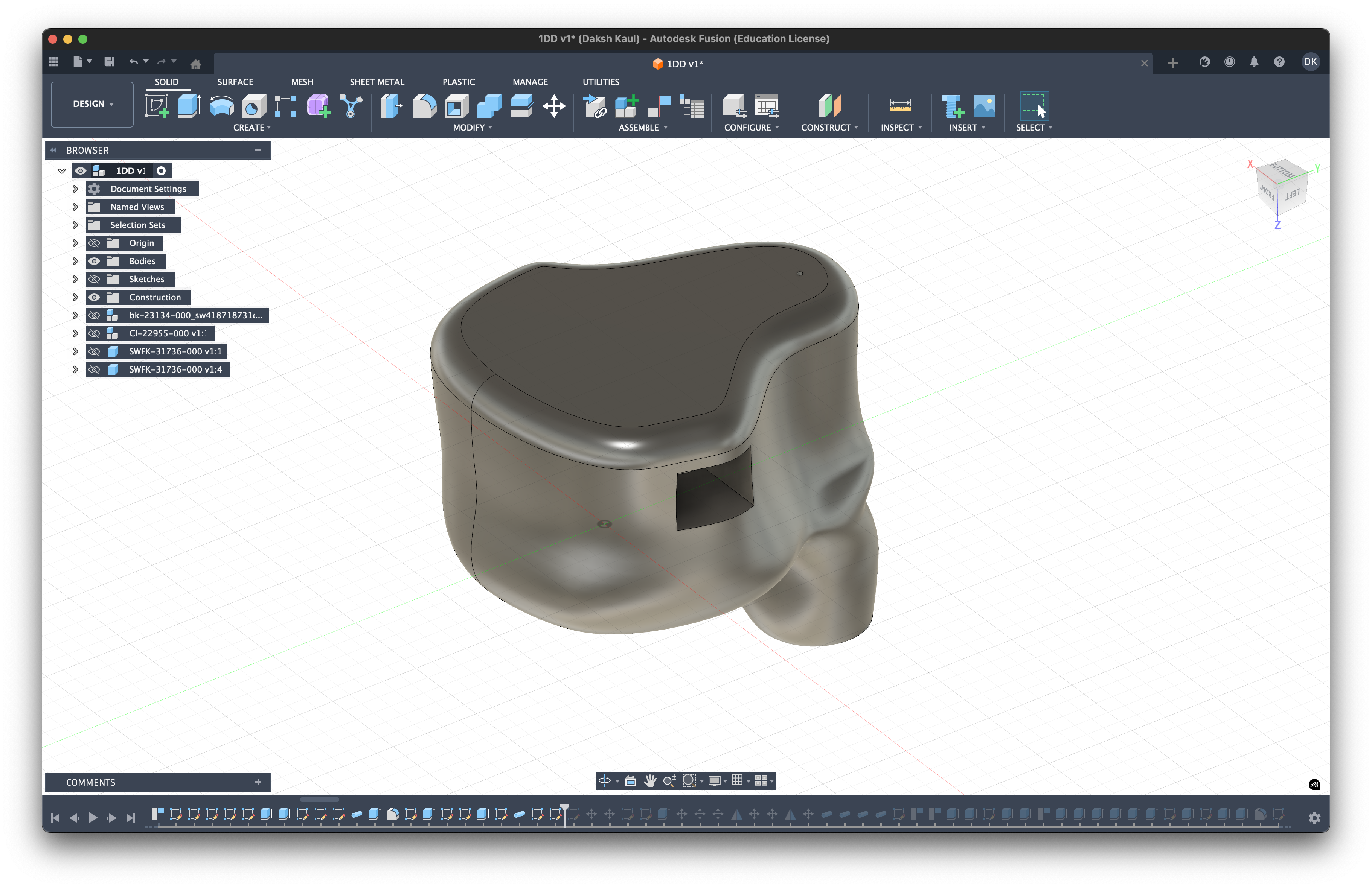
Phase 7: The Connector Cavity (2-Pin/MMCX)
The final piece of the puzzle is creating a home for your cable connector. Whether you are using a standard 0.78mm 2-Pin or an MMCX connector, the process is similar.
- Measure your Part: Utilizing measuring calipers, or via your parts spec sheet find or measure the width, depth, and height of your specific female socket.
- Create the Cut: Create a sketch on the flat top surface of the shell (where the cable exits). Draw a rectangle (for 2-pin) or circle (for MMCX) that matches your measurements.
- The Fit Strategy: You have two options here:
- Friction Fit: Design the hole slightly smaller than the connector, which allows you to build a volume that wraps around the connector walls so that it can grip onto the connector itself, thus snapping into place tightly.
- Resin Glue Fit (Recommended): Design the hole slightly larger (loose fit). You then fill the gap with a little UV resin or epoxy when inserting the connector. I found this method much better for prototyping because it reduces the stress on the shell walls and creates a perfect, airtight seal once cured.
Phase 8: Mirroring & Finalizing
Once you are happy with the Right ear shell, you don't need to redesign the Left one from scratch.
- Mirror: Use the Mirror tool in Fusion 360. Select your finished shell body and cap body, then select the appropriate origin plane as the mirror line.
- Export: You now have a perfectly symmetrical Left and Right pair ready for printing.
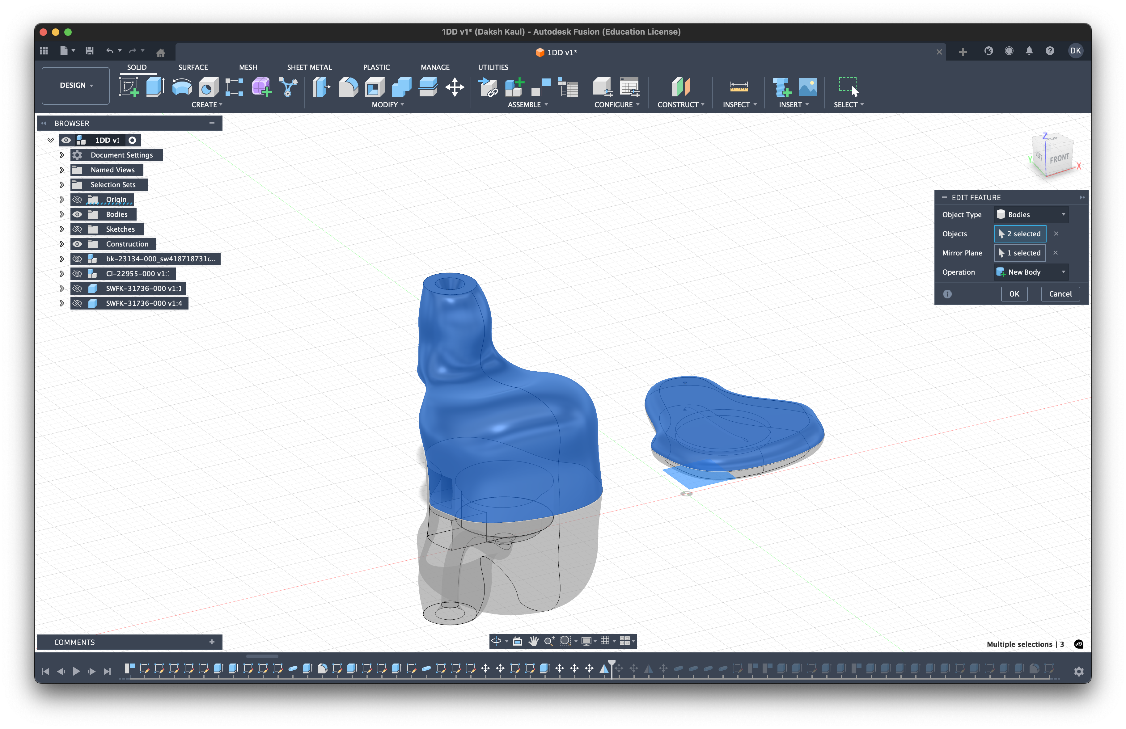
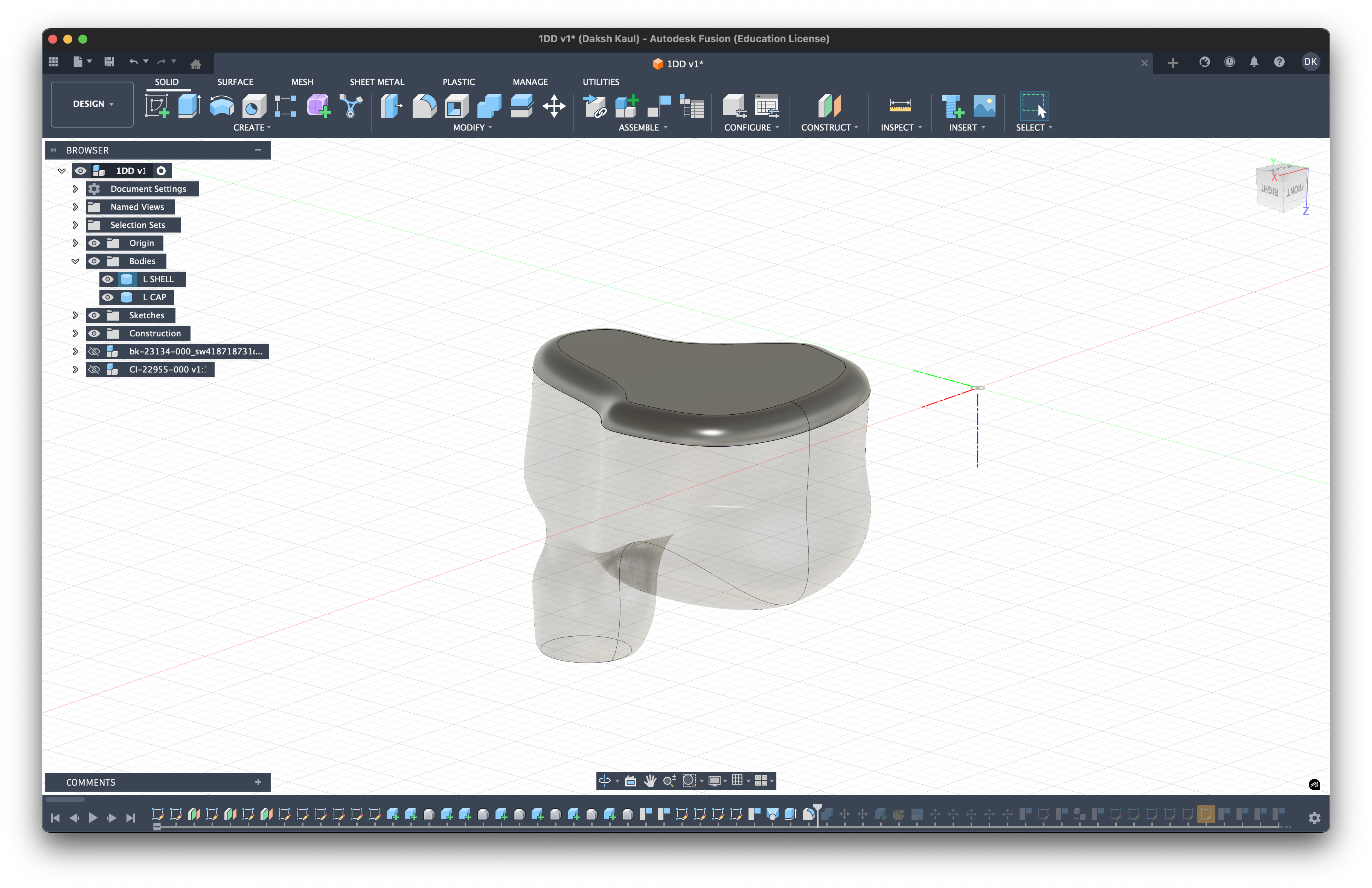
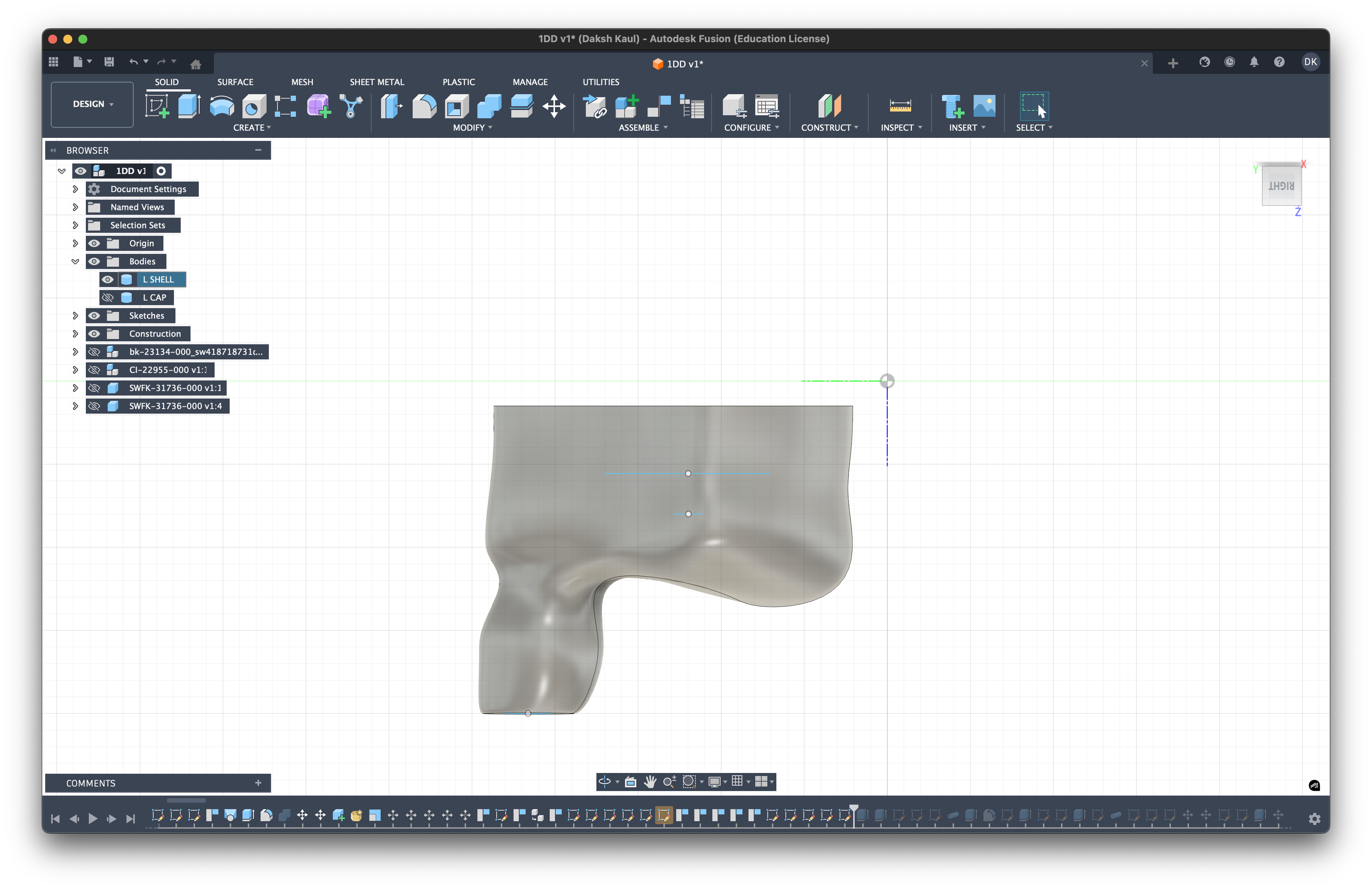
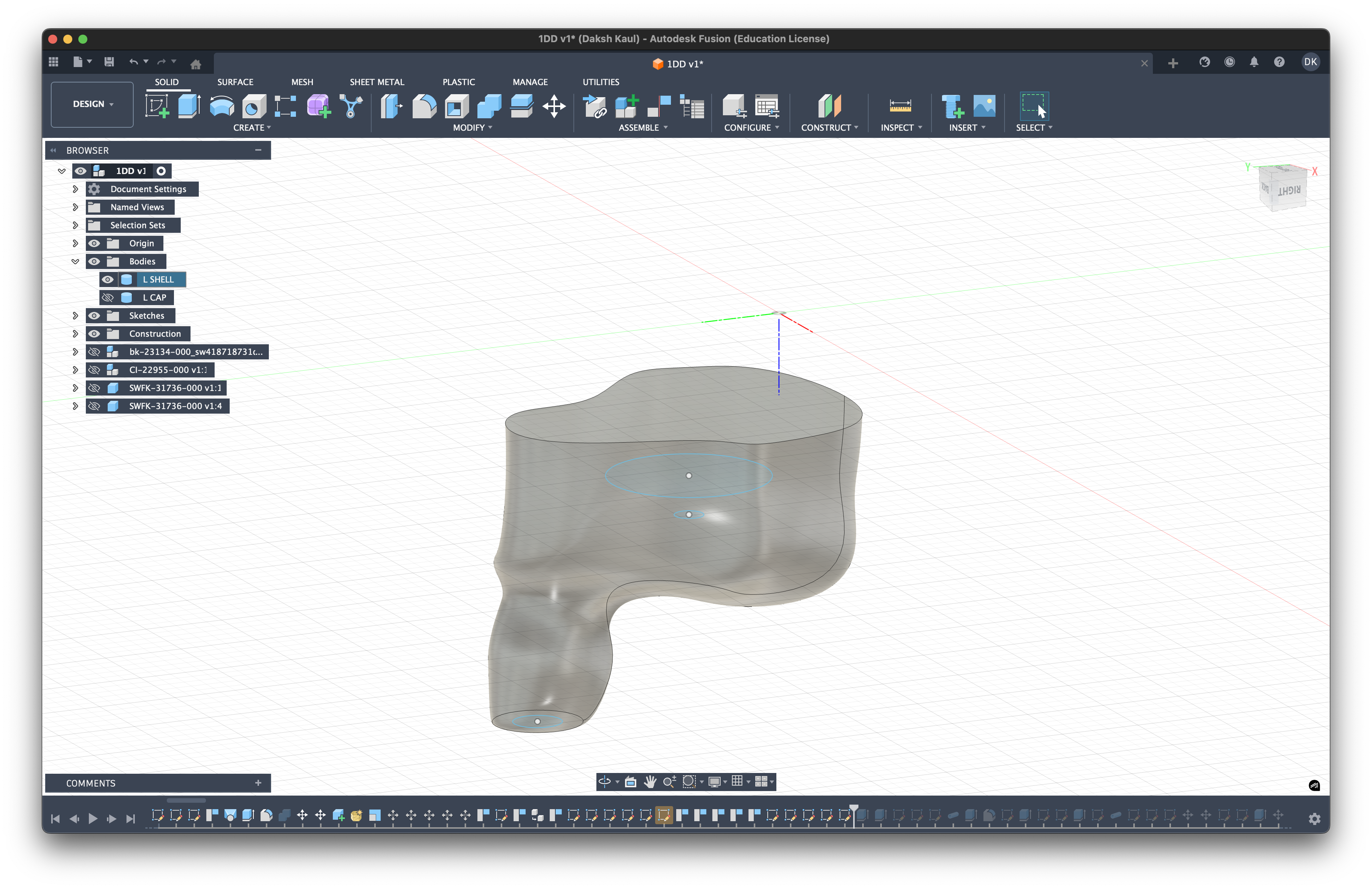
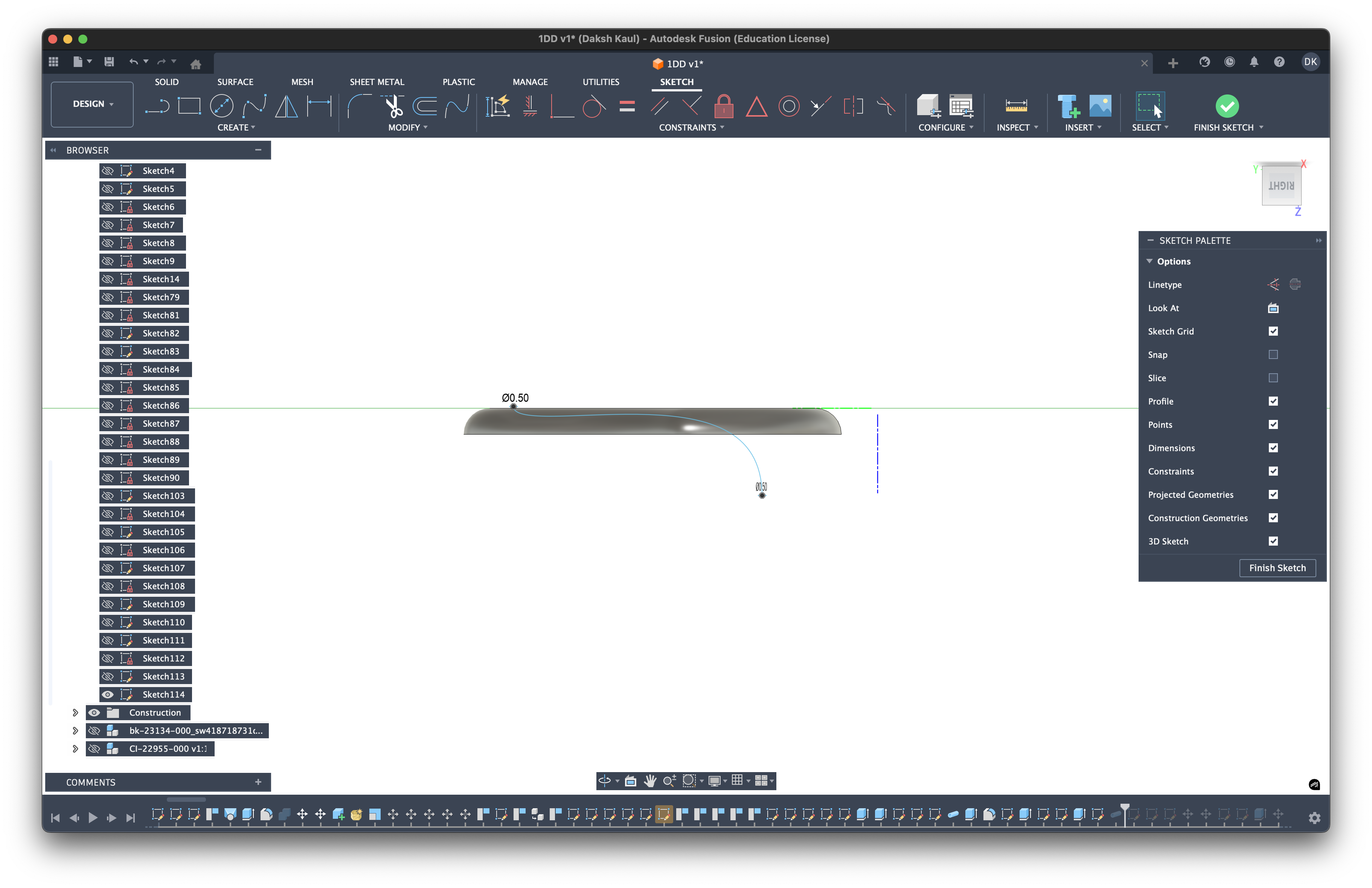
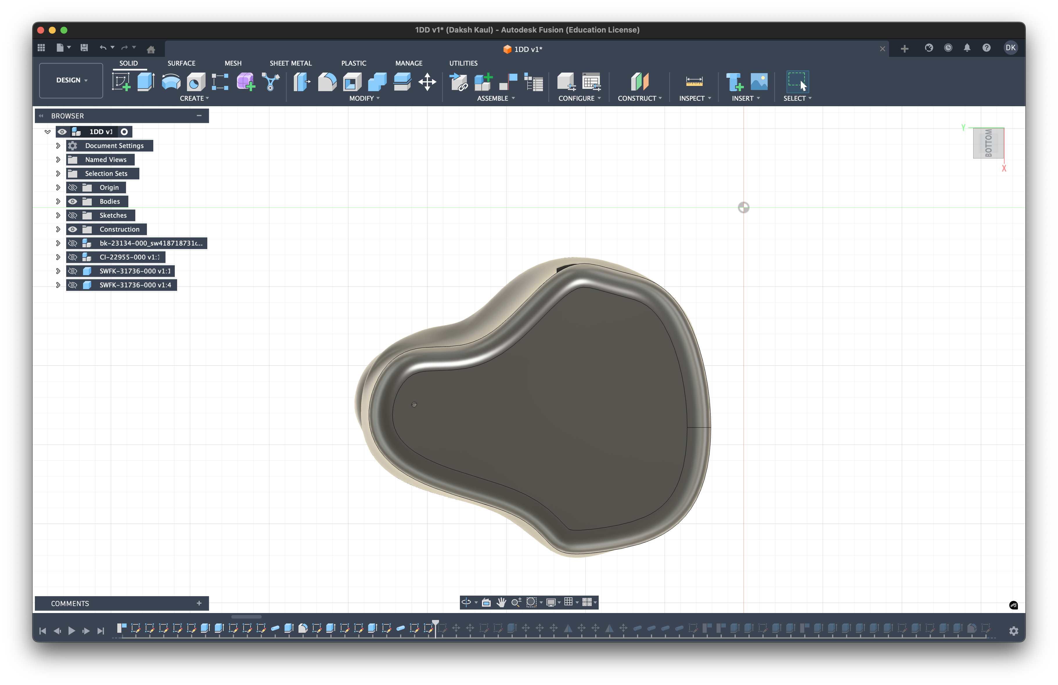
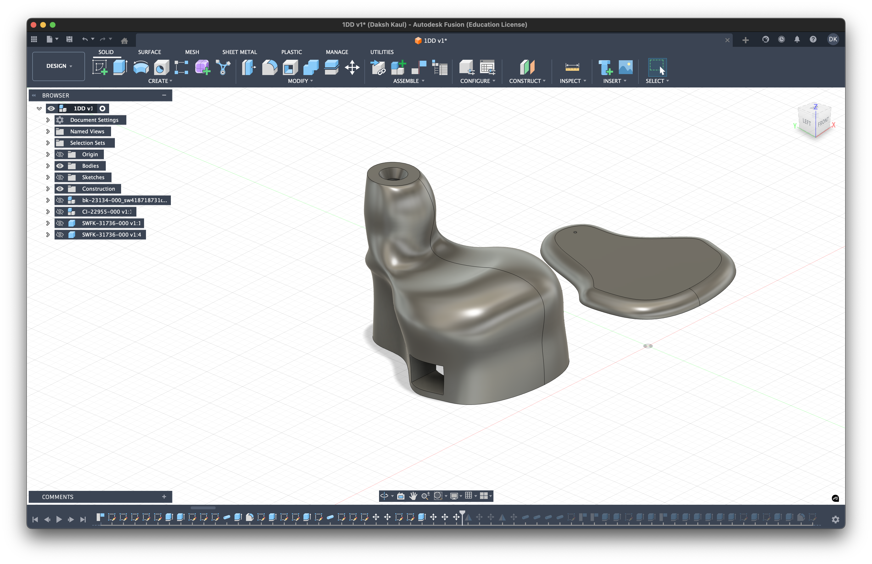
Finished Design: (Left side only)*
These are some of the screenshots of what your overall shell design should look like if you have followed along so far:
Citations
- "How To Design Custom In-Ear Monitors," YouTube, https://www.youtube.com/watch?v=y02BkH8inZA&list=PL4ahDGGN5zBFhmGqVUoBdOnjuF_9HXV5L&index=8 (accessed Dec. 28, 2025).
- "Helmholtz resonance," Wikipedia, https://en.wikipedia.org/wiki/Helmholtz_resonance (accessed Dec. 28, 2025).
- "Acoustic impedance," Wikipedia, https://en.wikipedia.org/wiki/Acoustic_impedance (accessed Dec. 28, 2025).
- "Young's modulus," Wikipedia, https://en.wikipedia.org/wiki/Young%27s_modulus (accessed Dec. 28, 2025).
- "Stereolithography," Wikipedia, https://en.wikipedia.org/wiki/Stereolithography (accessed Dec. 28, 2025).